XCARD XC-1A XMOS, XCARD XC-1A Datasheet - Page 7
XCARD XC-1A
Manufacturer Part Number
XCARD XC-1A
Description
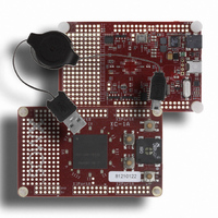
BOARD DEV KIT XS1-G4
Manufacturer
XMOS
Series
XCite™r
Type
MCUr
Specifications of XCARD XC-1A
Design Resources
XC-1A Schematic
Contents
Board, Cable
For Use With/related Products
XS1-G4
Lead Free Status / RoHS Status
Lead free / RoHS Compliant


XC-1A Hardware Manual (1.2)
The I/O pins of XCore1, XCore2 and XCore3 are brought out to expansion areas on
The expansion headers provide a bank of 12 I/O pins. The pins are mapped to the
5 I/O Expansion Areas [E]
both sides of the card. These areas have 0.1” pitch plated through holes and are
suitable for use with IDC headers. To provide maximum flexibility, no headers are
fitted, allowing the most suitable type to be selected. The routing of the I/O and
power pins in the expansion headers is shown below.
ports as shown in the table on the next page.
Eight pins from each bank can be configured as either two 4-bit ports or a single
8-bit port. Alternatively, two of the expansion headers can be used together as a
single 16-bit port.
X1D11
X2D11
X1D9
X1D7
X1D5
X1D3
X1D1
X2D9
X2D7
X2D5
X2D3
X2D1
GND
GND
GND
GND
16
16
2
2
15
15
1
1
5V
X1D10
X1D8
X1D6
3V3
X1D4
X1D2
X1D0
5V
X2D10
X2D8
X2D6
3V3
X2D4
X2D2
X2D0
www.xmos.com
X3D12
X3D14
X3D16
X3D18
X3D20
X2D22
X2D10
X3D0
X3D2
X3D4
X3D6
X3D8
3V3
3V3
5V
5V
1
15
1
15
16
16
2
2
X3D13
X3D15
X3D17
GND
X3D19
X3D21
X3D23
GND
X3D1
X3D3
X3D5
GND
X3D7
X3D9
X3D11
GND
7/18
Related parts for XCARD XC-1A
Image
Part Number
Description
Manufacturer
Datasheet
Request
R

Part Number:
Description:
BOARD DEV KIT XS1-G4 ETHERNET
Manufacturer:
XMOS
Datasheet:

Part Number:
Description:
DEV KIT EVENT-DRIVEN PROC XS1-L1
Manufacturer:
XMOS
Datasheet:

Part Number:
Description:
BOARD KIT XS1-G4 LED CTRL TILE
Manufacturer:
XMOS
Datasheet:

Part Number:
Description:
ADAPTER USB DEBUGGER JTAG XSYS2
Manufacturer:
XMOS
Datasheet:

Part Number:
Description:
BOARD DEV KIT XS1-G4
Manufacturer:
XMOS
Datasheet:

Part Number:
Description:
IC MPU 32BIT SINGLE CORE 64LQFP
Manufacturer:
XMOS
Datasheet:

Part Number:
Description:
IC MPU 32BIT SINGLE CORE 64LQFP
Manufacturer:
XMOS
Datasheet:
Part Number:
Description:
IC MPU 32BIT SINGLE CORE 64LQFP
Manufacturer:
XMOS
Datasheet:

Part Number:
Description:
IC MPU 32BIT SINGLE CORE 64LQFP
Manufacturer:
XMOS
Datasheet:
Part Number:
Description:
IC MPU 32BIT SINGLE CORE 64LQFP
Manufacturer:
XMOS
Datasheet:

Part Number:
Description:
IC MPU 32BIT SINGLE CORE 128TQFP
Manufacturer:
XMOS
Datasheet:
Part Number:
Description:
IC MPU 32BIT SINGLE CORE 64LQFP
Manufacturer:
XMOS
Datasheet:
Part Number:
Description:
IC MPU 32BIT SINGLE CORE 128TQFP
Manufacturer:
XMOS
Datasheet:
Part Number:
Description:
IC MPU 32BIT SINGLE CORE 128TQFP
Manufacturer:
XMOS
Datasheet:

Part Number:
Description:
IC MPU 32BIT DUAL CORE 124QFN
Manufacturer:
XMOS
Datasheet: