EFM32-G8XX-DK Energy Micro, EFM32-G8XX-DK Datasheet - Page 7
EFM32-G8XX-DK
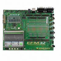
Manufacturer Part Number
EFM32-G8XX-DK
Description
KIT DEV EFM32 GECKO LCD SUPPORT
Manufacturer
Energy Micro
Series
EFM®32r
Type
MCUr
Datasheets
1.EFM32-G840F128-SK.pdf
(4 pages)
2.EFM32-G2XX-DK.pdf
(6 pages)
3.EFM32-G2XX-DK.pdf
(3 pages)
4.EFM32-G2XX-DK.pdf
(10 pages)
5.EFM32-G8XX-DK.pdf
(70 pages)
6.EFM32-G8XX-DK.pdf
(14 pages)
7.EFM32-G8XX-DK.pdf
(3 pages)
Specifications of EFM32-G8XX-DK
Contents
Motherboard, MCU Board, Prototyping Board, Cable, CD
Processor To Be Evaluated
EFM32G8x
Data Bus Width
32 bit
Interface Type
RS-232, USB, I2C
Maximum Operating Temperature
+ 85 C
Minimum Operating Temperature
- 40 C
Operating Supply Voltage
5 V
Silicon Manufacturer
Energy Micro
Core Architecture
ARM
Core Sub-architecture
Cortex-M3
Silicon Family Name
Gecko
Kit Contents
Mother Board, Prototyping Board, MCU Board, Software Development Environment
Rohs Compliant
Yes
Silicon Core Number
EFM32
For Use With/related Products
EFM32G890F128
Lead Free Status / RoHS Status
Lead free / RoHS Compliant
Other names
914-1001
Available stocks
Company
Part Number
Manufacturer
Quantity
Price
Company:

Part Number:
EFM32-G8XX-DK
Manufacturer:
EnergyMi
Quantity:
13


6 Peripherals
6.1 Pushbuttons
6.2 DIP switches
6.3 Joystick
6.4 LEDs
6.5 Differential analog input
6.6 Single ended analog inputs
6.7 Line in / Audio in
2010-04-09 - t0005_1.10
The development kit has a rich set of user programmable peripherals that allows most of the EFM32G
on-chip peripherals to be evaluated and tested.
The registers referred to in this chapter are accessible using the kit Board Support Package. Refer to
the BSP chapter in this manual to learn how to enable the motherboard peripherals. A reference to all
the registers and their function is in the Board Controller chapter.
The state of the pushbuttons marked SW1 to SW4 can be read from the board controller, using the
PUSHBUTTON register. The buttons are debounced by RC filters with a time constant of 1ms.
The dipswitch positions can be read from the board controller, using the DIPSWITCH register. The
switches are not debounced.
The joystick position can be read from the board controller, using the JOYSTICK register. The positions
are debounced by RC filters with a time constant of 1ms.
The user LEDs can be set by the board controller by writing to the LED register. The state of the LEDs
can also be read back.
This BNC input signal is converted to a differential signal by a differential operational amplifier using
ground as reference.The op amp output common mode voltage is 1.65V, and also implements a low-
pass active filter with a 3dB cutoff frequency of 4MHz.
The common mode voltage can be changed by adjusting the R5 and R12 resistors. It can also be
controlled by the VCM pin on the EFM if a shunt resistor is soldered in place of R252 and R5 and R12
are removed.
The peripheral is connected directly to the EFM when the ANALOG_DIFF bit in the PERCTRL register
in the board controller has been set.
This peripheral connects the two BNCs to the ADC on the EFM, and can be used as a single ended
analog interface. It can also be used for digital I/O.
The peripheral is connected directly to the EFM when the ANALOG_SE bit in the PERCTRL register in
the board controller has been set.
This is an audio input amplifier with filter, and the output connects to the ADC of the EFM. The gain
of the amplifier is 0 dB and the bias point is 1.65 V. The filter is a 3-pole linear phase MFB filter with
a cutoff frequency of 20 kHz. In addition to the input amplifier and filter, the line in is equipped with a
voltage divider resulting in 6dB attenuation.
Preliminary
...the world's most energy friendly microcontrollers
7
www.energymicro.com
Related parts for EFM32-G8XX-DK
Image
Part Number
Description
Manufacturer
Datasheet
Request
R

Part Number:
Description:
KIT STARTER EFM32 GECKO
Manufacturer:
Energy Micro
Datasheet:

Part Number:
Description:
BOARD PROTOTYPING FOR EFM32
Manufacturer:
Energy Micro
Datasheet:

Part Number:
Description:
KIT DEVELOPMENT EFM32 GECKO
Manufacturer:
Energy Micro
Datasheet:

Part Number:
Description:
MCU, MPU & DSP Development Tools TG840 Sample Kit
Manufacturer:
Energy Micro
Datasheet:

Part Number:
Description:
MCU, MPU & DSP Development Tools TG Starter Kit
Manufacturer:
Energy Micro
Datasheet:
Part Number:
Description:
MCU, MPU & DSP Development Tools TG108 Sample Kit
Manufacturer:
Energy Micro
Part Number:
Description:
MCU, MPU & DSP Development Tools TG210 Sample Kit
Manufacturer:
Energy Micro
Datasheet:
Part Number:
Description:
MCU, MPU & DSP Development Tools TG822 Sample Kit
Manufacturer:
Energy Micro
Datasheet:
Part Number:
Description:
MCU, MPU & DSP Development Tools TG230 Sample Kit
Manufacturer:
Energy Micro

Part Number:
Description:
SAMPLE KIT (SMALL BOX - CONTAINING 2 DEVICES)
Manufacturer:
Energy Micro
Part Number:
Description:
SAMPLE KIT (SMALL BOX - CONTAINING 2 DEVICES)
Manufacturer:
Energy Micro