ATEVK1104S Atmel, ATEVK1104S Datasheet - Page 65
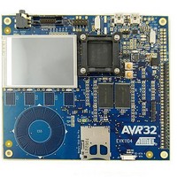
ATEVK1104S
Manufacturer Part Number
ATEVK1104S
Description
KIT EVAL FOR AT32UC
Manufacturer
Atmel
Series
AVR®32 UC3r
Type
MCUr
Specifications of ATEVK1104S
Contents
Board, Cables
Tool Type
Development Kit
Cpu Core
AVR 32
Data Bus Width
32 bit
Processor Series
AT32
Processor To Be Evaluated
AT32UC3A3256S
Interface Type
USB, JTAG, SD Card, Nexus, MMC
Core Architecture
AVR
Operating Supply Voltage
5.5 V
For Use With/related Products
*
Lead Free Status / RoHS Status
Lead free / RoHS Compliant


Figure 10-6. SMC Signals for NRD and NRW Controlled Accesses.
10.10.2
Table 10-35. SDRAM Clock Signal.
Note:
Table 10-36. SDRAM Clock Signal
32072C–AVR32–2010/03
A0/A1/NBS[3:0]
Symbol
1/(t
Symbol
SDRAMC
SDRAMC
SDRAMC
SDRAMC
SDRAMC
SDRAMC
SDRAMC
SDRAMC
SDRAMC
SDRAMC
SDRAMC
SDRAMC
CPSDCK
D0 - D15
A2-A25
NWE
NRD
NCS
1. The maximum frequency of the SDRAMC interface is the same as the max frequency for the HSB.
)
1
2
3
4
5
6
7
8
9
10
11
12
SDRAM Signals
Parameter
SDRAM Controller Clock Frequency
Parameter
SDCKE High before SDCK Rising Edge
SDCKE Low after SDCK Rising Edge
SDCKE Low before SDCK Rising Edge
SDCKE High after SDCK Rising Edge
SDCS Low before SDCK Rising Edge
SDCS High after SDCK Rising Edge
RAS Low before SDCK Rising Edge
RAS High after SDCK Rising Edge
SDA10 Change before SDCK Rising Edge
SDA10 Change after SDCK Rising Edge
Address Change before SDCK Rising Edge
Address Change after SDCK Rising Edge
These timings are given for 10 pF load on SDCK and 40 pF on other signals.
SMC9
SMC19
SMC7
SMC20
SMC3
SMC4
SMC5
SMC6
SMC8
SMC45
SMC43
SMC42
SMC37
SMC38
SMC39
SMC40
SMC41
SMC44
Conditions
Conditions
SMC9
SMC1
SMC2
SMC8
SMC7
SMC3
SMC4
SMC5
SMC6
Min.
Min.
7.4
3.2
2.9
7.5
1.6
7.2
2.3
7.6
1.9
6.2
2.2
7
AT32UC3A3/A4
SMC33
1/(t
SMC23
Max.
Max.
cpcpu
(1)
SMC24
SMC32
)
SMC31
SMC25
SMC26
SMC29
SMC30
MHz
Unit
Unit
ns
ns
ns
ns
ns
ns
ns
ns
ns
ns
ns
ns
65
Related parts for ATEVK1104S
Image
Part Number
Description
Manufacturer
Datasheet
Request
R

Part Number:
Description:
DEV KIT FOR AVR/AVR32
Manufacturer:
Atmel
Datasheet:

Part Number:
Description:
INTERVAL AND WIPE/WASH WIPER CONTROL IC WITH DELAY
Manufacturer:
ATMEL Corporation
Datasheet:
Part Number:
Description:
Low-Voltage Voice-Switched IC for Hands-Free Operation
Manufacturer:
ATMEL Corporation
Datasheet:
Part Number:
Description:
MONOLITHIC INTEGRATED FEATUREPHONE CIRCUIT
Manufacturer:
ATMEL Corporation
Datasheet:
Part Number:
Description:
AM-FM Receiver IC U4255BM-M
Manufacturer:
ATMEL Corporation
Datasheet:
Part Number:
Description:
Monolithic Integrated Feature Phone Circuit
Manufacturer:
ATMEL Corporation
Datasheet:
Part Number:
Description:
Multistandard Video-IF and Quasi Parallel Sound Processing
Manufacturer:
ATMEL Corporation
Datasheet:
Part Number:
Description:
High-performance EE PLD
Manufacturer:
ATMEL Corporation
Datasheet:
Part Number:
Description:
8-bit Flash Microcontroller
Manufacturer:
ATMEL Corporation
Datasheet:
Part Number:
Description:
2-Wire Serial EEPROM
Manufacturer:
ATMEL Corporation
Datasheet: