45205 Parallax Inc, 45205 Datasheet - Page 121
45205
Manufacturer Part Number
45205
Description
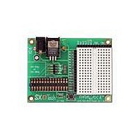
SX TECH BOARD
Manufacturer
Parallax Inc
Type
MCUr
Datasheet
1.45180.pdf
(184 pages)
Specifications of 45205
Contents
Board
For Use With/related Products
SX MCUs
For Use With
28825 - MINI SOUND PLAYER SOUNDPAL130-28029 - KIT PARTS SMART SENSORS
Lead Free Status / Rohs Status
Lead free / RoHS Compliant


13 Appendix C: SX Instruction Set
13.1 Introduction
The columns of each instruction definition table in this appendix contain important information about
the instruction’s behavior, size and structure.
The Command column lists all the available forms of the given command. The operands in lower-case
letters indicate a symbol or value should be inserted in their place. The operands in upper-case letters
should be entered exactly as seen. For example, the following form of the MOV command:
The operands are described in Table 26 - Symbol and Value Operands, below.
The Words column indicates the number of 12-bit EEPROM words consumed by the instruction.
The Cycles column indicates the number of clock cycles the given instruction will take. The number
outside of parenthesis is the number of cycles in Turbo mode. The number inside parenthesis is the
number of cycles in non-Turbo mode (compatibility mode).
should be entered into code (assuming $A5 is the desired literal) as follows:
MOV !OPTION, #literal
MOV !OPTION, #$A5
Symbol
addr8
addr9
addr12
fr
#literal
M
op.bit
!OPTION
PC
!port
W
!WDT
An 8-bit address symbol or value
A 9-bit address symbol or value
An 11-bit (SX20/28) or 12-bit (SX48/52) address symbol or value
A file register
A literal value (‘#’ must precede value)
The mode register
The specified bit of the specified operand
The option register
The program counter
The specified I/O port data direction reg.
The working register
The watchdog register
Definition
Table 26 - Symbol and Value Operands
13 Appendix C: SX Instruction Set
SX-Key/Blitz Development System Manual 2.0 Parallax, Inc. Page 121
Related parts for 45205
Image
Part Number
Description
Manufacturer
Datasheet
Request
R

Part Number:
Description:
D-Subminiature Connectors DB9 Male Connector
Manufacturer:
Parallax Inc


Part Number:
Description:
Microcontroller Modules & Accessories DISCONTINUED BY PARALLAX
Manufacturer:
Parallax Inc

Part Number:
Description:
BOOK UNDERSTANDING SIGNALS
Manufacturer:
Parallax Inc
Datasheet:


Part Number:
Description:
COMPETITION RING FOR SUMOBOT
Manufacturer:
Parallax Inc
Datasheet:


Part Number:
Description:
TEXT INFRARED REMOTE FOR BOE-BOT
Manufacturer:
Parallax Inc
Datasheet:
Part Number:
Description:
Microcontroller Modules & Accessories DISCONTINUED BY PARALLAX
Manufacturer:
Parallax Inc
Part Number:
Description:
BOOK UNDERSTANDING SIGNALS
Manufacturer:
Parallax Inc
Datasheet:
Part Number:
Description:
BOARD EXPERIMENT+LCD NX-1000
Manufacturer:
Parallax Inc
Datasheet:
Part Number:
Description:
IC MCU 2K FLASH 50MHZ SO-18
Manufacturer:
Parallax Inc
Datasheet: