Z8F083A0128ZCOG Zilog, Z8F083A0128ZCOG Datasheet - Page 2
Z8F083A0128ZCOG
Manufacturer Part Number
Z8F083A0128ZCOG
Description
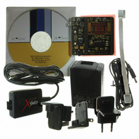
KIT DEVELOPMENT F083A
Manufacturer
Zilog
Series
Z8 Encore! XP®r
Type
MCUr
Specifications of Z8F083A0128ZCOG
Contents
Hardware, Software and Documentation
For Use With/related Products
Z8F083A
For Use With
269-4661 - KIT ACC ETHERNET SMART CABLE
Lead Free Status / RoHS Status
Lead free / RoHS Compliant
Other names
269-4672
Available stocks
Company
Part Number
Manufacturer
Quantity
Price
Company:

Part Number:
Z8F083A0128ZCOG
Manufacturer:
Zilog
Quantity:
1


Flash Memory Programming Overview
Flash Test Mode
PRS001003-1207
Setup
Zilog’s Z8 Encore!
products, based on the 8-bit eZ8 CPU. Z8 Encore!
Zilog’s extensive line of 8-bit microcontrollers. The Flash in-circuit programming
capability allows the faster development time and program changes in the field. The new
eZ8 CPU is upward compatible with existing Z8
set of Z8 Encore! F083x series makes it suitable for a variety of applications including
motor control, security systems, home appliances, personal electronic devices, and
sensors.
The on-chip Flash controller can be bypassed, allowing direct control of the Flash signals
through the general purpose input/output (GPIO) pins. The Flash memory can be
programmed faster by controlling the Flash memory signals directly. This method is
beneficial when programming a large number of devices and is helpful to those who are
developing the multi-site gang programmers.
Z8 Encore! F083x reuses most of the existing test modes from Z8 Encore! XP F0822
Series Flash Microcontrollers. It supports the following modes for programming the
Flash:
•
•
Only one of the above test modes can be selected at a time. Multiple combinations result
in pin conflicts. Each test mode is enabled by setting the corresponding enable bit in the
on-chip debugger’s (OCD’s) test mode register. Flash test mode can also be enabled by
pulling the TESTMODE pad Low if certain conditions on the option bit states are
satisfied.
Flash test mode allows testing of the Flash memory. It is used at wafer level testing by
UMC with the VPP pin to improve programming/erase times. It is also used on packaged
part without the use of the VPP pin.
The setup conditions required for the Flash test mode are:
1. Apply Vdd = 3.3 V type (UMC specification), AVDD = 3.3 V.
2. Drive the TESTMODE pad Low.
3. Wait for the Power-On Reset (POR) to exit. POR is clocked by an internal RC
Flash Test Mode
Bypassing the Flash Controller
oscillator and lasts approximately 5 ms after the brown-out threshold is passed.
®
MCU family of products are the first in line of Zilog microcontroller
®
®
CPU instructions. The rich peripheral
F083x series of products expand on
Z8 Encore!
®
F083x Series
Page 2 of 25
Related parts for Z8F083A0128ZCOG
Image
Part Number
Description
Manufacturer
Datasheet
Request
R

Part Number:
Description:
Communication Controllers, ZILOG INTELLIGENT PERIPHERAL CONTROLLER (ZIP)
Manufacturer:
Zilog, Inc.
Datasheet:

Part Number:
Description:
KIT DEV FOR Z8 ENCORE 16K TO 64K
Manufacturer:
Zilog
Datasheet:

Part Number:
Description:
KIT DEV Z8 ENCORE XP 28-PIN
Manufacturer:
Zilog
Datasheet:

Part Number:
Description:
DEV KIT FOR Z8 ENCORE 8K/4K
Manufacturer:
Zilog
Datasheet:

Part Number:
Description:
KIT DEV Z8 ENCORE XP 28-PIN
Manufacturer:
Zilog
Datasheet:

Part Number:
Description:
DEV KIT FOR Z8 ENCORE 4K TO 8K
Manufacturer:
Zilog
Datasheet:
Part Number:
Description:
CMOS Z8 microcontroller. ROM 16 Kbytes, RAM 256 bytes, speed 16 MHz, 32 lines I/O, 3.0V to 5.5V
Manufacturer:
Zilog, Inc.
Datasheet:
Part Number:
Description:
Low-cost microcontroller. 512 bytes ROM, 61 bytes RAM, 8 MHz
Manufacturer:
Zilog, Inc.
Datasheet:
Part Number:
Description:
Z8 4K OTP Microcontroller
Manufacturer:
Zilog, Inc.
Datasheet:
Part Number:
Description:
CMOS SUPER8 ROMLESS MCU
Manufacturer:
Zilog, Inc.
Datasheet:
Part Number:
Description:
SL1866 CMOSZ8 OTP Microcontroller
Manufacturer:
Zilog, Inc.
Datasheet:
Part Number:
Description:
SL1866 CMOSZ8 OTP Microcontroller
Manufacturer:
Zilog, Inc.
Datasheet:
Part Number:
Description:
OTP (KB) = 1, RAM = 125, Speed = 12, I/O = 14, 8-bit Timers = 2, Comm Interfaces Other Features = Por, LV Protect, Voltage = 4.5-5.5V
Manufacturer:
Zilog, Inc.
Datasheet:
Part Number:
Description:
Manufacturer:
Zilog, Inc.
Datasheet: