TOOLSTICK540DC Silicon Laboratories Inc, TOOLSTICK540DC Datasheet
TOOLSTICK540DC
Specifications of TOOLSTICK540DC


Related parts for TOOLSTICK540DC


TOOLSTICK540DC Summary of contents
Page 1
Handling Recommendations To enable development, the ToolStick Base Adapter and daughter cards are distributed without any protective plastics. To prevent ...
Page 2
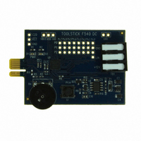
ToolStick-F 54 0DC 2. Contents The ToolStick-F540DC kit contains the ToolStick C8051F540 Daughter Card. A ToolStick daughter card requires a ToolStick Base Adapter to communicate with the PC. ToolStick Base Adapters can be purchased at www.silabs.com/toolstick. 3. ToolStick Overview The ...
Page 3
Getting Started The necessary software to download, debug, and communicate with the target microcontroller must be downloaded from www.silabs.com/toolstick. The following software is necessary to build a project, download code to, and communicate with the target microcontroller: Silicon ...
Page 4
ToolStick-F 54 0DC 5.2. Keil Demonstration Toolset 5.2.1. Keil Assembler and Linker The Keil demonstration toolset assembler and linker place no restrictions on code size. 5.2.2. Keil Demonstration C51 C Compiler The evaluation version of the C51 compiler is the ...
Page 5
Keil µVision Silicon Labs Drivers As an alternative to the Silicon Labs IDE, the µVision debug driver allows the Keil µVision IDEs to communicate with Silicon Labs on-chip debug logic. In-system Flash memory programming integrated into the driver allows ...
Page 6
ToolStick-F 54 0DC 6. ToolStick C8051F540 Daughter Card Features Demo The ToolStick kit includes a few simple code examples. The example described in this section is titled F540DC_FeaturesDemo. The purpose of this example is to guide a new user through ...
Page 7
Connecting to the Device and Downloading Firmware This section describes how to open the IDE, open and build a project, connect to a device and download the firmware. 1. Open the Silicon Labs IDE from the Start Programs ...
Page 8
ToolStick-F 54 0DC 6.4. Viewing and Modifying Registers All registers on the device can be viewed and modified when the device halted state. The registers are grouped together according to which peripheral or part of hardware they ...
Page 9
Enabling and Using Watch Windows The Debug Windows in the View menu are used to view and modify hardware registers. To view and modify variables in code, the IDE provides Watch Windows. Just as with register debug windows, variables ...
Page 10
ToolStick-F 54 0DC 6.6. Setting and Running to Breakpoints The Silicon Labs microcontroller devices support up to four hardware breakpoints. A breakpoint is associated with a specific line of code. When the processor reaches a hardware breakpoint, the code execution ...
Page 11
Single-Stepping through Firmware The IDE supports the ability to single-step through firmware one assembly instruction at a time. The IDE reads the Flash from the device, converts the instructions to assembly and displays them in a disassembly window. The ...
Page 12
ToolStick-F 54 0DC the ToolStick Settings menu. 4. Under “Pin Settings”, change GPIO0 / RTS to “GPIO Output - Push Pull” and click “OK.” The rest of the default settings are correct for the C8051F540 Features Demo. ...
Page 13
Additional Demo Examples In addition to the F540DC_FeaturesDemo example firmware, the ToolStick download package also includes a demo project named F540DC_ADC0_TemperatureSensor. The instructions for running this demo can be found at the top of the source file. The project ...
Page 14
ToolStick-F 54 0DC 10. C8051F540 Daughter Card Schematic 14 Rev. 0.1 ...
Page 15
N : OTES ToolStick-F540DC Rev. 0.1 15 ...
Page 16
... Should Buyer purchase or use Silicon Laboratories products for any such unintended or unauthorized ap- plication, Buyer shall indemnify and hold Silicon Laboratories harmless against all claims and damages. Silicon Laboratories and Silicon Labs are trademarks of Silicon Laboratories Inc. Other products or brandnames mentioned herein are trademarks or registered trademarks of their respective holders. ...