TOOLSTICK540DC Silicon Laboratories Inc, TOOLSTICK540DC Datasheet - Page 9
TOOLSTICK540DC
Manufacturer Part Number
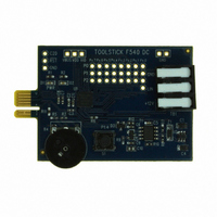
TOOLSTICK540DC
Description
DAUGHTER CARD TOOLSTICK F540
Manufacturer
Silicon Laboratories Inc
Series
ToolStickr
Type
MCUr
Datasheets
1.TOOLSTICK540DC.pdf
(274 pages)
2.TOOLSTICK540DC.pdf
(16 pages)
3.TOOLSTICK540DC.pdf
(12 pages)
Specifications of TOOLSTICK540DC
Contents
Daughter Card
Processor To Be Evaluated
C8051F54x
Processor Series
C8051F54x
Interface Type
USB
Operating Supply Voltage
2.7 V to 3.6 V
Lead Free Status / RoHS Status
Lead free / RoHS Compliant
For Use With/related Products
C8051F54x
For Use With
336-1345 - TOOLSTICK BASE ADAPTER336-1182 - ADAPTER USB DEBUG FOR C8051FXXX
Lead Free Status / Rohs Status
Lead free / RoHS Compliant
Other names
336-1717


6.5. Enabling and Using Watch Windows
The Debug Windows in the View menu are used to view and modify hardware registers. To view and modify
variables in code, the IDE provides Watch Windows. Just as with register debug windows, variables in the watch
windows are updated each time the device is halted. This section of the User’s Guide explains how to add a
variable to the watch window and modify the variable. In the F540_FeaturesDemo example code, the variable
Num_LED_Flashes is a counter that stores the number of times the LED blinks.
1. If the device is running, stop execution using the “Stop” button or use the Debug Stop menu option.
2. In the File View on the left-hand side of the IDE, double-click on F540DC_FeaturesDemo.c to open the source
3. Scroll to the Timer3_ISR() function and right-click on the variable “Num_LED_Flashes.” In the context menu
4. Start and stop the device a few times. See that the value of the Num_LED_Flashes is incremented each time
5. When the device is halted, click on the value field in the watch window and change the value to 0. Then click the
6. Start and stop the device a few times to watch the variable increment starting at 0.
Changing the values of variables does not require recompiling the code and redownloading the firmware. At any
time, the device can be halted and the values of the variables can be changed. The firmware will continue
execution using the new values.
file.
that appears, select “Add Num_LED_Flashes to Watch” and then choose “Default Default Type.” On the
right-hand portion of the IDE, the watch window appears and the variable is added. The current value of the
variable is shown to the right of the name.
the LED blinks.
Refresh button or select Debug Refresh to write the new value to the device.
Rev. 0.1
ToolStick-F540DC
9
Related parts for TOOLSTICK540DC
Image
Part Number
Description
Manufacturer
Datasheet
Request
R

Part Number:
Description:
KIT TOOL EVAL SYS IN A USB STICK
Manufacturer:
Silicon Laboratories Inc
Datasheet:

Part Number:
Description:
TOOLSTICK DEBUG ADAPTER
Manufacturer:
Silicon Laboratories Inc
Datasheet:

Part Number:
Description:
TOOLSTICK BASE ADAPTER
Manufacturer:
Silicon Laboratories Inc
Datasheet:

Part Number:
Description:
TOOLSTICK DAUGHTER CARD
Manufacturer:
Silicon Laboratories Inc
Datasheet:

Part Number:
Description:
TOOLSTICK DAUGHTER CARD
Manufacturer:
Silicon Laboratories Inc
Datasheet:

Part Number:
Description:
TOOLSTICK DAUGHTER CARD
Manufacturer:
Silicon Laboratories Inc
Datasheet:

Part Number:
Description:
TOOLSTICK PROGRAMMING ADAPTER
Manufacturer:
Silicon Laboratories Inc
Datasheet:

Part Number:
Description:
TOOLSTICK DAUGHTER CARD
Manufacturer:
Silicon Laboratories Inc
Datasheet:

Part Number:
Description:
KIT STARTER TOOLSTICK
Manufacturer:
Silicon Laboratories Inc
Datasheet:

Part Number:
Description:
KIT UNIVERSITY TOOLSTICK STARTER
Manufacturer:
Silicon Laboratories Inc
Datasheet:

Part Number:
Description:
DAUGHTER CARD TOOLSTICK F330
Manufacturer:
Silicon Laboratories Inc
Datasheet:

Part Number:
Description:
CARD DAUGHTER UNIVRSTY TOOLSTICK
Manufacturer:
Silicon Laboratories Inc
Datasheet:

Part Number:
Description:
DAUGHTER CARD TOOLSTICK F582
Manufacturer:
Silicon Laboratories Inc
Datasheet:

Part Number:
Description:
DAUGHTER CARD TOOLSTICK F500
Manufacturer:
Silicon Laboratories Inc
Datasheet:

Part Number:
Description:
DAUGHTER CARD TOOLSTICK F560
Manufacturer:
Silicon Laboratories Inc
Datasheet: