MC56F8006DEMO Freescale Semiconductor, MC56F8006DEMO Datasheet - Page 7
MC56F8006DEMO
Manufacturer Part Number
MC56F8006DEMO
Description
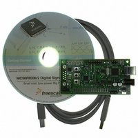
DEMO BOARD FOR MC56F8006
Manufacturer
Freescale Semiconductor
Type
DSPr
Datasheets
1.MC56F8006DEMO.pdf
(13 pages)
2.MC56F8006DEMO.pdf
(8 pages)
3.MC56F8006DEMO.pdf
(2 pages)
4.MC56F8006DEMO.pdf
(100 pages)
Specifications of MC56F8006DEMO
Contents
Board
Processor To Be Evaluated
MC56F8006
Interface Type
RS-232, USB
Operating Supply Voltage
3.3 V
Silicon Manufacturer
Freescale
Core Architecture
56800/E
Core Sub-architecture
56800/E
Silicon Core Number
MC56F
Silicon Family Name
MC56F80xx
Rohs Compliant
Yes
For Use With/related Products
MC56F8006
Lead Free Status / RoHS Status
Lead free / RoHS Compliant


2.2.2 IRQ_SW1 and IRQ_SW2 Push Switches
Push switches SW1 and SW2 provide an active low signal when depressed to MCF56F8006
ports PB2 and PB3 respectively. See options JP1 and JP2 to change the input ports applied.
2.2.3 Y2 Crystal Reference
Y2 provides a location for an external 32 kHz can crystal to be applied to the MC56F8006. Refer
to the device user manual for crystal application information. Components R47, R48, C40 and
C41 must also be applied with the crystal. Refer to the MC56F8006DEMO schematic diagram for
component connection details.
2.3 Ports and Connectors
2.3.1 J4: USB port
J4 will provide a single connection to power the MC56F8006DEMO board. Supporting host
software for basic operation is provided on the support DVD. The current release will provide a
virtual serial terminal port.
2.3.1.1 STATUS and TPWR Indicators
These indicators provide USB operation status indication. Status will flash or blink to indicate
operation. TPWR will be on when target power is enabled from the USB port.
2.3.2 PWR Jack
This connector provides external power input to the board. The PWR jack accepts a standard
2.0 ~ 2.1 mm center barrel plug connector (positive voltage center) to apply a +VIN supply of +5
VDC to +12V. Also review option jumper JP3 and JP4 operation for power application. External
power is not required when applying the USB development port, J4.2.3.2.1 POWER Indicator The
POWER indicator will be on when the MC56F8006DEMO board has +3.3V available for operation.
2.3.3 +3.3 V and GND Test Points
Test point pads are provided for access to VSS/Ground and the +3.3V power signal on the board.
2.3.4 COM Port
The COM port connector and supporting interface circuit is not populated by default. The USB
development port J4 may provide serial port connection to the MC56F8006 SCI if wanted. Refer
to the TX_EN and RX_EN option jumpers and the J4 USB BDM connection for more details.
Components required to apply the COM port are following:
• U2: MAX3232CPWR, TI or same, note
• COM: Generic 9 pin D-Sub connector, R/A female or socket type, .318 mount hole to PCB
pin distance
• C7, C8, C9, C10 and C11: SMT 0805 0.1 μF X7R 50V capacitors
www.freescale.com
7
Related parts for MC56F8006DEMO
Image
Part Number
Description
Manufacturer
Datasheet
Request
R

Part Number:
Description:
Manufacturer:
Freescale Semiconductor, Inc
Datasheet:
Part Number:
Description:
Manufacturer:
Freescale Semiconductor, Inc
Datasheet:
Part Number:
Description:
Manufacturer:
Freescale Semiconductor, Inc
Datasheet:
Part Number:
Description:
Manufacturer:
Freescale Semiconductor, Inc
Datasheet:
Part Number:
Description:
Manufacturer:
Freescale Semiconductor, Inc
Datasheet:
Part Number:
Description:
Manufacturer:
Freescale Semiconductor, Inc
Datasheet:
Part Number:
Description:
Manufacturer:
Freescale Semiconductor, Inc
Datasheet:
Part Number:
Description:
Manufacturer:
Freescale Semiconductor, Inc
Datasheet:
Part Number:
Description:
Manufacturer:
Freescale Semiconductor, Inc
Datasheet:
Part Number:
Description:
Manufacturer:
Freescale Semiconductor, Inc
Datasheet:
Part Number:
Description:
Manufacturer:
Freescale Semiconductor, Inc
Datasheet:
Part Number:
Description:
Manufacturer:
Freescale Semiconductor, Inc
Datasheet:
Part Number:
Description:
Manufacturer:
Freescale Semiconductor, Inc
Datasheet:
Part Number:
Description:
Manufacturer:
Freescale Semiconductor, Inc
Datasheet:
Part Number:
Description:
Manufacturer:
Freescale Semiconductor, Inc
Datasheet: