DEMO9S08SF4 Freescale Semiconductor, DEMO9S08SF4 Datasheet - Page 10
DEMO9S08SF4
Manufacturer Part Number
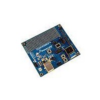
DEMO9S08SF4
Description
BOARD DEMO FOR S08SF4
Manufacturer
Freescale Semiconductor
Type
MCUr
Datasheet
1.DEMO9S08SF4.pdf
(12 pages)
Specifications of DEMO9S08SF4
Contents
Board
Processor To Be Evaluated
S08
Data Bus Width
8 bit
Interface Type
USB
Operating Supply Voltage
5 V
Silicon Manufacturer
Freescale
Core Architecture
HCS08
Core Sub-architecture
HCS08
Silicon Core Number
MC9S08
Silicon Family Name
S08SF
Kit Contents
Board, USB A-to-B Cable, Get Started DVD, Printed
Rohs Compliant
Yes
For Use With/related Products
MC9S08SF4
Lead Free Status / RoHS Status
Lead free / RoHS Compliant


D E M O 9 S 0 8 S F 4
J U N E
9 ,
2 0 0 9
U S E R
G U I D E
TIMING
Default timing for the DEMO9S08SF4 is provided by the MC9S08SF4 internal timing source
which is active out of RESET. Refer to the MC9S08SF4 Reference Manual for details on
configuring the timing source.
COMMUNICATIONS
The MC9S08SF4 does not support serial communications.
No board support for this
functionality is provided.
USER OPTIONS
The DEMO9S08SF4 includes various input and output devices to aid application development
and debug.
User I/O includes 2 momentary pushbutton switches, 1 potentiometer, 1
temperature sensor, and 1 piezo buzzer. Each device may be enabled or disabled individually
with the USER1 option header. Each user enable is clearly marked as to functionality.
Pushbutton Switches
Two push button switches provide momentary, active-low input, for user applications. Pull-ups
internal to the MCU must be enabled to provide error free operation. Pushbutton switches
SW1 and SW2 are enabled to the MCU I/O ports by the USER1 option bank. Figure 5 below
shows the user jumper settings and MCU connections.
Potentiometer
A 5k ohm, thumb-wheel type, potentiometer at RV1 provides variable resistance input for user
applications. The output is the result of a voltage divider that changes as the thumb-wheel is
turned. The potentiometer is connected between VDD and GND with the center tap providing
the divider output. Figure 5 below shows the user jumper settings and MCU connection.
Temperature Sensor
A surface-mount, NTC thermistor (B = 3900) is installed at location RZ1. This component
provides a voltage input to the MCU inversely proportional to temperature. Figure 5 below
shows the user jumper settings and MCU connections.
10
Related parts for DEMO9S08SF4
Image
Part Number
Description
Manufacturer
Datasheet
Request
R

Part Number:
Description:
Manufacturer:
STMicroelectronics
Datasheet:

Part Number:
Description:
DEMO BOARD FOR HMC6042/HMC1041Z
Manufacturer:
Honeywell Microelectronics & Precision Sensors

Part Number:
Description:
DEMO BOARD FOR HMC1042L/HMC1041Z
Manufacturer:
Honeywell Microelectronics & Precision Sensors
Datasheet:

Part Number:
Description:
KIT DEMO 4 SENSOR CHAN RS232
Manufacturer:
VTI Technologies
Datasheet:


Part Number:
Description:
DEMO: DC Power Supply, 32 Volts, 3 Amps
Manufacturer:
Tektronix
Part Number:
Description:
DEMO: Programmable DC Power Supply, 32 Volts, 3 Amps
Manufacturer:
Tektronix

Part Number:
Description:
Manufacturer:
Freescale Semiconductor, Inc
Datasheet:
Part Number:
Description:
Manufacturer:
Freescale Semiconductor, Inc
Datasheet:
Part Number:
Description:
Manufacturer:
Freescale Semiconductor, Inc
Datasheet:
Part Number:
Description:
Manufacturer:
Freescale Semiconductor, Inc
Datasheet:
Part Number:
Description:
Manufacturer:
Freescale Semiconductor, Inc
Datasheet:
Part Number:
Description:
Manufacturer:
Freescale Semiconductor, Inc
Datasheet:
Part Number:
Description:
Manufacturer:
Freescale Semiconductor, Inc
Datasheet:
Part Number:
Description:
Manufacturer:
Freescale Semiconductor, Inc
Datasheet: