DEMO9S08SF4 Freescale Semiconductor, DEMO9S08SF4 Datasheet - Page 7
DEMO9S08SF4
Manufacturer Part Number
DEMO9S08SF4
Description
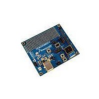
BOARD DEMO FOR S08SF4
Manufacturer
Freescale Semiconductor
Type
MCUr
Datasheet
1.DEMO9S08SF4.pdf
(12 pages)
Specifications of DEMO9S08SF4
Contents
Board
Processor To Be Evaluated
S08
Data Bus Width
8 bit
Interface Type
USB
Operating Supply Voltage
5 V
Silicon Manufacturer
Freescale
Core Architecture
HCS08
Core Sub-architecture
HCS08
Silicon Core Number
MC9S08
Silicon Family Name
S08SF
Kit Contents
Board, USB A-to-B Cable, Get Started DVD, Printed
Rohs Compliant
Yes
For Use With/related Products
MC9S08SF4
Lead Free Status / RoHS Status
Lead free / RoHS Compliant


U S E R
DEVELOPMENT SUPPORT
Application development and debug for the target MC9S08SF4 is supported through the
integrated, Open-Source Background Debug Mode (USB-BDM) interface. An optional 6-pos
BDM_PORT header allows connecting an external HCS12/HCS08 BDM cable. This header is
not installed in default configurations.
Integrated BDM
The DEMO9S08SF4 board features an integrated Open Source BDM (USB-BDM) based on
the Freescale MC9S08JM60 MCU.
development and debugging via background debug mode and provides primary power to the
development module. The integrated BDM is fully supported by CodeWarrior development
tools.
The integrated USB BDM provides power and ground to the target board eliminating the need
to power the board externally. Power from the USB BDM is derived from the USB bus. The
integrated USB BDM is designed to sink a maximum of 300mA of current from the USB bus.
Therefore, total current consumption for the target board, and connected circuitry, must not
exceed 300mA. This current limit describes the current supplied by the USB cable to the
BDM circuit, the target board, and any connected circuitry. Excessive current drain will violate
the USB specification causing the bus to disconnect. Damage to the host PC USB hub or the
target board may result.
BDM_PORT Header
A compatible HCS12 BDM cable may also attach to the 6-pin BDM interface header
(BDM_PORT). Figure 2 below shows the pin-out for the BDM_PORT header.
Figure 2: BDM_PORT Header
POWER
The DEMO9S08SF4 may be powered from the integrated USB-BDM or from the MCU IO
connector at J1. The USB-BDM is designed to supply either +5VDC or +3.3VDC to the target
MCU. The VOUT_SEL option jumper at JP1 selects the desired output voltage.
Power may also be applied to connector J1 or the board may be configured to supply power
from connector J1 to external circuitry.
G U I D E
NOTE: The BDM_PORT header is not installed in default configuration.
BKGD 1
3
5
2 GND
4 RESET*
6 VDD
See the MC9S08SF4 Reference Manual for details
The integrated USB BDM supports application
7
Related parts for DEMO9S08SF4
Image
Part Number
Description
Manufacturer
Datasheet
Request
R

Part Number:
Description:
Manufacturer:
STMicroelectronics
Datasheet:

Part Number:
Description:
DEMO BOARD FOR HMC6042/HMC1041Z
Manufacturer:
Honeywell Microelectronics & Precision Sensors

Part Number:
Description:
DEMO BOARD FOR HMC1042L/HMC1041Z
Manufacturer:
Honeywell Microelectronics & Precision Sensors
Datasheet:

Part Number:
Description:
KIT DEMO 4 SENSOR CHAN RS232
Manufacturer:
VTI Technologies
Datasheet:


Part Number:
Description:
DEMO: DC Power Supply, 32 Volts, 3 Amps
Manufacturer:
Tektronix
Part Number:
Description:
DEMO: Programmable DC Power Supply, 32 Volts, 3 Amps
Manufacturer:
Tektronix

Part Number:
Description:
Manufacturer:
Freescale Semiconductor, Inc
Datasheet:
Part Number:
Description:
Manufacturer:
Freescale Semiconductor, Inc
Datasheet:
Part Number:
Description:
Manufacturer:
Freescale Semiconductor, Inc
Datasheet:
Part Number:
Description:
Manufacturer:
Freescale Semiconductor, Inc
Datasheet:
Part Number:
Description:
Manufacturer:
Freescale Semiconductor, Inc
Datasheet:
Part Number:
Description:
Manufacturer:
Freescale Semiconductor, Inc
Datasheet:
Part Number:
Description:
Manufacturer:
Freescale Semiconductor, Inc
Datasheet:
Part Number:
Description:
Manufacturer:
Freescale Semiconductor, Inc
Datasheet: