DEMO51AC256KIT Freescale Semiconductor, DEMO51AC256KIT Datasheet - Page 16
DEMO51AC256KIT
Manufacturer Part Number
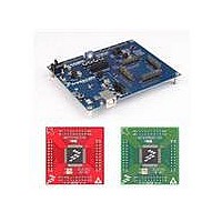
DEMO51AC256KIT
Description
KIT DEMO DEMOAC DC9S08A
Manufacturer
Freescale Semiconductor
Series
Flexis™r
Type
MCUr
Specifications of DEMO51AC256KIT
Contents
*
Processor To Be Evaluated
HCS08
Interface Type
USB
Operating Supply Voltage
5 V
Silicon Manufacturer
Freescale
Core Architecture
Coldfire
Core Sub-architecture
Coldfire V1
Silicon Core Number
MCF51
Silicon Family Name
Flexis - MCF51AC
Kit Contents
Board
Rohs Compliant
Yes
For Use With/related Products
MCF51AC256
Lead Free Status / RoHS Status
Lead free / RoHS Compliant


D E M O A C
TROUBLESHOOTING
The DEMOAC is fully tested and operational before shipping. If it fails to function properly, in-
spect the board for obvious physical damage first. Verify the communications setup as de-
scribed under GETTING STARTED.
Initial Flash Programming
To program target device FLASH initially, or if device FLASH is erased, apply external power
at the PWR jack and set the PWR_SEL option header to VR1. When prompted by P&E soft-
ware to cycle target power, move the PWRSW to the OFF position momentarily then to the ON
position. Otherwise, the BDM will fail to connect to the target device.
Most common problems are related to improperly configured options or communications pa-
rameters.
1.
2.
3.
4.
5.
6.
7.
Contact
complete description of the problem.
If the simulator software requires a device power cycle during FLASH programming, en-
sure the board is powered externally and the PWR_SEL option header is set to VR1.
Verify the +5V voltage indicator is ON.
Verify input power is connected. If powered from an external power source, measure at
least +7V between VR2-1 and VR2-2 using a multi-meter. If powered from the integrated
BDM, measure +5V across capacitor C16
Ensure the PWRSW is in the ON position.
Verify default option jumper settings and RESET the board.
Ensure target module is securely, and correctly, seated on pin headers JM1 – JM4.
If a peripheral feature does not function properly, ensure all USER select jumpers are in-
stalled.
support@axman.com
U S E R
G U I D E
by email for further assistance. Provide board name and a
16
A P R I L
1 0 ,
2 0 0 8
Related parts for DEMO51AC256KIT
Image
Part Number
Description
Manufacturer
Datasheet
Request
R

Part Number:
Description:
Manufacturer:
Freescale Semiconductor, Inc
Datasheet:
Part Number:
Description:
Manufacturer:
Freescale Semiconductor, Inc
Datasheet:
Part Number:
Description:
Manufacturer:
Freescale Semiconductor, Inc
Datasheet:
Part Number:
Description:
Manufacturer:
Freescale Semiconductor, Inc
Datasheet:
Part Number:
Description:
Manufacturer:
Freescale Semiconductor, Inc
Datasheet:
Part Number:
Description:
Manufacturer:
Freescale Semiconductor, Inc
Datasheet:
Part Number:
Description:
Manufacturer:
Freescale Semiconductor, Inc
Datasheet:
Part Number:
Description:
Manufacturer:
Freescale Semiconductor, Inc
Datasheet:
Part Number:
Description:
Manufacturer:
Freescale Semiconductor, Inc
Datasheet:
Part Number:
Description:
Manufacturer:
Freescale Semiconductor, Inc
Datasheet:
Part Number:
Description:
Manufacturer:
Freescale Semiconductor, Inc
Datasheet:
Part Number:
Description:
Manufacturer:
Freescale Semiconductor, Inc
Datasheet:
Part Number:
Description:
Manufacturer:
Freescale Semiconductor, Inc
Datasheet:
Part Number:
Description:
Manufacturer:
Freescale Semiconductor, Inc
Datasheet:
Part Number:
Description:
Manufacturer:
Freescale Semiconductor, Inc
Datasheet: