DEMO51AC256KIT Freescale Semiconductor, DEMO51AC256KIT Datasheet - Page 9
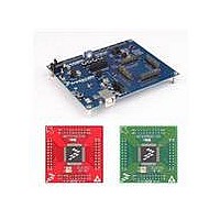
DEMO51AC256KIT
Manufacturer Part Number
DEMO51AC256KIT
Description
KIT DEMO DEMOAC DC9S08A
Manufacturer
Freescale Semiconductor
Series
Flexis™r
Type
MCUr
Specifications of DEMO51AC256KIT
Contents
*
Processor To Be Evaluated
HCS08
Interface Type
USB
Operating Supply Voltage
5 V
Silicon Manufacturer
Freescale
Core Architecture
Coldfire
Core Sub-architecture
Coldfire V1
Silicon Core Number
MCF51
Silicon Family Name
Flexis - MCF51AC
Kit Contents
Board
Rohs Compliant
Yes
For Use With/related Products
MCF51AC256
Lead Free Status / RoHS Status
Lead free / RoHS Compliant


D E M O A C
Figure 3: PWR_SEL Option Header
VX_EN Option Header
The VX_EN option header is a 2-pin jumper that connects the target-board voltage rail to IO
connector position J1-1. IO connector position J1-3 connects directly to the ground plane.
This input requires a regulated +5.0V voltage source. This power input is decoupled to mini-
mize noise input but is not regulated. Also, no protection is applied on this input and damage
to the target board may result if over-driven. Do not attempt to power the target board through
this connector while also applying power through the PWR connector as damage to the board
may result.
Power may be sourced to off-board circuitry through the MCU_PORT. The current limitation of
the on-board regulator must be considered when attempting to source power to external cir-
cuitry. Excessive current drain may damage the target board or the on-board regulator. The
figure below shows the VX_EN option header connections.
Figure 4: VX_EN Option Header
MCU Power
Each power input is routed through an option header. The option header is not installed in
default configurations and a cut-trace on each power input provides default connections. To
BDM
BDM
NOTE: The voltage regulator reference designator at the PWR_SEL option header does not
CAUTION: Do not apply power to connector J1 while also sourcing power from either the
NOTE: Do not exceed available current supply from on-board regulator when sourcing power
PWR_SEL
PWR_SEL
VX_EN
VX_EN
•
•
▪
U S E R
▪
• •
• •
match the reference designator of the voltage regulator.
through connector J1 to external circuitry.
ON
OFF
VR1
VR1
G U I D E
PWR connector. Damage to the board may result.
Enable power connection to connector J1
Disable power connection to connector J1
Selects input voltage from POWER connector
NOTE: The VR1 input is connected to the regulator at VR2.
This is an error in the board silkscreen.
Selects input voltage from the integrated BDM
9
A P R I L
1 0 ,
2 0 0 8
Related parts for DEMO51AC256KIT
Image
Part Number
Description
Manufacturer
Datasheet
Request
R

Part Number:
Description:
Manufacturer:
Freescale Semiconductor, Inc
Datasheet:
Part Number:
Description:
Manufacturer:
Freescale Semiconductor, Inc
Datasheet:
Part Number:
Description:
Manufacturer:
Freescale Semiconductor, Inc
Datasheet:
Part Number:
Description:
Manufacturer:
Freescale Semiconductor, Inc
Datasheet:
Part Number:
Description:
Manufacturer:
Freescale Semiconductor, Inc
Datasheet:
Part Number:
Description:
Manufacturer:
Freescale Semiconductor, Inc
Datasheet:
Part Number:
Description:
Manufacturer:
Freescale Semiconductor, Inc
Datasheet:
Part Number:
Description:
Manufacturer:
Freescale Semiconductor, Inc
Datasheet:
Part Number:
Description:
Manufacturer:
Freescale Semiconductor, Inc
Datasheet:
Part Number:
Description:
Manufacturer:
Freescale Semiconductor, Inc
Datasheet:
Part Number:
Description:
Manufacturer:
Freescale Semiconductor, Inc
Datasheet:
Part Number:
Description:
Manufacturer:
Freescale Semiconductor, Inc
Datasheet:
Part Number:
Description:
Manufacturer:
Freescale Semiconductor, Inc
Datasheet:
Part Number:
Description:
Manufacturer:
Freescale Semiconductor, Inc
Datasheet:
Part Number:
Description:
Manufacturer:
Freescale Semiconductor, Inc
Datasheet: