MC56F8006DEMO-T Freescale Semiconductor, MC56F8006DEMO-T Datasheet - Page 6
MC56F8006DEMO-T
Manufacturer Part Number
MC56F8006DEMO-T
Description
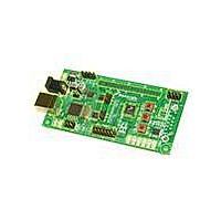
BOARD DEMO FOR MC56F8006 DSP
Manufacturer
Freescale Semiconductor
Specifications of MC56F8006DEMO-T
Processor To Be Evaluated
MC56F8006
Interface Type
RS-232, USB
Operating Supply Voltage
3.3 V
Peak Reflow Compatible (260 C)
Yes
Tool / Board Applications
General Purpose MCU, MPU, DSP, DSC
Mcu Supported Families
MC56F8006 Series
Leaded Process Compatible
Yes
Rohs Compliant
Yes
Lead Free Status / RoHS Status
Lead free / RoHS Compliant


Chapter 2
Technical Summary
2.1 Options
2.1.1 JP1: IRQ_SW1 Input Select
JP1 is a cutaway type option on the bottom side of the DEMO board. Default connection is to
MC56F8006 I/O port B2. Optional connection to port B4 is provided for user application.
2.1.2 JP2: IRQ_SW2 Input Select
JP2 is a cutaway type option on the bottom side of the DEMO board. Default connection is to
MC56F8006 I/O port B3. Optional connection to port B5 is provided for user application.
2.1.3 JP3: +3.3 V Enable
JP3 option installed (default) provides +3.3V regulated voltage from the onboard VR1 voltage
regulator to power the DEMO board. Open this option to power the board from an external +3.3V
source or from the J1 connector.
2.1.4 JP4: +Vopt Enable
JP4 option installed provides a connection from J1 pin 1 to the board +3.3V power connection.
This option is open/idle by default. This option may be applied to provide board +3.3 V regulated
voltage to the J1 connector (JP3 installed also) or to source +3.3V from J1 (JP3 open) to power
the board from a connected host platform.
2.1.5 TX_EN and RX_EN Option Jumpers
TX_EN and RX_EN options provide selection of the serial port connection for the MC56F8006 SCI
serial port. MC56F8006 ports B6 (RXD) and B7 (TXD) provide the SCI I/O pins for these options.
Default option setting is for the USB port to support the SCI serial port. The RS-232 serial port is
not populated by default but may be applied by the user if populated.
TX_EN and RX_EN = position 1–2 default, USB BDM serial port support.
Position 2–3 = RS-232 port.
See the support DVD for virtual terminal software to support the USB serial port.
2.2 User Components
2.2.1 LED1: 6 Indicators
Six indicator LEDs are provided for user application indications. The LEDs are applied to the
MC56F8006 I/O port A0/PWM0 to A5/PWM5 signals. Buffers are applied so that the LEDs will not
load the I/O port pins during operation. LEDs are on during the applied signals logic high level.
The following table provides the signal and LED reference.
LED
LED1
LED2
LED3
LED4
LED5
LED6
6
MC56F8006 I/O Port
PAO/PWM0
PA1/PWM1
PA2/PWM2
PA3/PWM3
PA4/PWM4
PA5/PWM5
LED Color
RED
RED
GREEN
GREEN
YELLOW
YELLOW
www.freescale.com
Related parts for MC56F8006DEMO-T
Image
Part Number
Description
Manufacturer
Datasheet
Request
R

Part Number:
Description:
Digital Signal Controller
Manufacturer:
Freescale Semiconductor, Inc
Datasheet:
Part Number:
Description:
Manufacturer:
Freescale Semiconductor, Inc
Datasheet:
Part Number:
Description:
Manufacturer:
Freescale Semiconductor, Inc
Datasheet:
Part Number:
Description:
Manufacturer:
Freescale Semiconductor, Inc
Datasheet:
Part Number:
Description:
Manufacturer:
Freescale Semiconductor, Inc
Datasheet:
Part Number:
Description:
Manufacturer:
Freescale Semiconductor, Inc
Datasheet:
Part Number:
Description:
Manufacturer:
Freescale Semiconductor, Inc
Datasheet:
Part Number:
Description:
Manufacturer:
Freescale Semiconductor, Inc
Datasheet:
Part Number:
Description:
Manufacturer:
Freescale Semiconductor, Inc
Datasheet:
Part Number:
Description:
Manufacturer:
Freescale Semiconductor, Inc
Datasheet:
Part Number:
Description:
Manufacturer:
Freescale Semiconductor, Inc
Datasheet:
Part Number:
Description:
Manufacturer:
Freescale Semiconductor, Inc
Datasheet:
Part Number:
Description:
Manufacturer:
Freescale Semiconductor, Inc
Datasheet:
Part Number:
Description:
Manufacturer:
Freescale Semiconductor, Inc
Datasheet:
Part Number:
Description:
Manufacturer:
Freescale Semiconductor, Inc
Datasheet: