3DK1657 Renesas Electronics America, 3DK1657 Datasheet
3DK1657
Specifications of 3DK1657


Related parts for 3DK1657


3DK1657 Summary of contents
Page 1
... U M SER F H8SX/1657 ICROCONTROLLER Check the silkscreen around the power jack (J9) for the minimum and maximum voltage input levels for this 3DK. Always use a centre positive supply for this board. DO NOT USE AN E6000 POWER SUPPLY with this 3DK ANUAL - N CHIP ...
Page 2
Preface Cautions 1. This document may be, wholly or partially, subject to change without notice. 2. All rights reserved. No one is permitted to reproduce or duplicate, in any form, a part or this entire document without Renesas Technology Europe ...
Page 3
T C ABLE OF ONTENTS T C .......................................................................................................................................................3 ABLE OF ONTENTS ..........................................................................................................................................4 OWER EQUIREMENTS 2. P – ........................................................................................................................................4 OWER P EHAVIOUR 3. P ...............................................................................................................................................................4 URPOSE ......................................................................................................................................................4 OARD AYOUT ....................................................................................................................................................5 ...
Page 4
P R OWER EQUIREMENTS All 3DK boards are centre positive with a 2.5mm barrel power jack. The diode, D1 provides reverse polarity protection. A 9V, centre positive supply is suitable for use with this board. Warning Check the silkscreen ...
Page 5
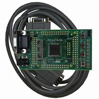
BOOT LATCH U2 HC74 dual D-type logic LOCK IAGRAM Diagram x.1 is representative of the 3DK components and their connectivity. Power Jack & Regulator IC Generic Headers Flash/Boot Header Micon Headers Serial Connector Debug Header Potentiometer 6. ...
Page 6
L EDS There are nine LEDs on the 3DK board. The green BOOT LED indicates the device is in boot mode when lit. The eight red LEDs are connected port and will light when their corresponding ...
Page 7
J UMPERS Table 6-3 below describes the function of the 2-Pin jumpers contained on this 3DK board. Reference Jumper Function J10 RX Disable PRXD from the RS232 device enabled. This enables serial port communication. J11 UVCC ...
Page 8
... The user may place the H8SX/1657 device provided on a 3DK1657 board in user boot mode by fitting jumper J13. The Boot procedure must then be performed for entry into user boot mode. The Boot LED should light, suggesting a transition to user boot mode ...
Page 9
Programming Port Table – Programming port pins and their 3DK signal names SCI4 3DK Signal Name Table 9-1: Serial Port Boot Channel 9. ORT ROGRAMMING The microcontroller must enter boot mode for programming, and the programming port must ...
Page 10
H EADERS 10. ICON EADERS Table 10-1 to Table 10-4 shows the micon headers and their corresponding microcontroller connections. The header pins connect directly to the micon pin unless otherwise stated. J1 Circuit Net Name Pin 1 ...
Page 11
J3 Circuit Net Name Pin 1 PH7 3 PI0 5 PI2 7 GROUND 9 PI5 11 PI7 13 P11 15 P13 17 RESn 19 P14 21 WDTOVFn 23 XTAL 25 BOARD_VCC 27 P17 29 PTXD J1 Circuit Net Name Pin ...
Page 12
G H ENERIC EADERS Table 10-5below shows the generic header connections 19 way generic Header Pin Generic 3DK Signal Name Number Header Name 1 Supply Supply 2 Xin CON_EXTAL 3 Vcc Board_VCC 4 Vss Ground 5 Vcc Board_VCC 6 ...
Page 13
B S REAKPOINT UPPORT The device has no break controller. No breakpoints can be located in ROM code. However, code located in RAM may have multiple breakpoints limited only by the size of the On-Chip RAM. 11.4. C RAM ...
Page 14
H'0000 Vectors H'0800 CUser_Vectors H'0803 H'1000 UGenU FDT Kernel H'1E63 H'3000 PHMON CHMON H'5863 On-Chip FLASH ROM H'BFFFF H'FF6000 On-Chip RAM H'FF6494 BHMON H'FF66B2 H'FFBE00 Stack H'FFBFFF H'FFFB80 Internal I/O REGISTERS H'FFFFFF 11. AUD ATE ETTING HMON ...
Page 15
This value is held in the HMONserialconfiguser.c file, as SCI_CFG_BRR (see the Serial Port section for baud rate register setting values). The project must be re-built and the resulting code downloaded to the microcontroller once ...