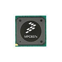
MPC8377E-RDBA Freescale Semiconductor, MPC8377E-RDBA Datasheet - Page 70

MPC8377E-RDBA
Manufacturer Part Number
MPC8377E-RDBA
Description
BOARD REF DES MPC8377 REV 2.1
Manufacturer
Freescale Semiconductor
Series
PowerQUICC II™ PROr
Type
MPUr
Datasheets
1.MPC8377EVRAGD.pdf
(126 pages)
2.MPC8377EVRAGD.pdf
(2 pages)
3.MPC8377E-RDBA.pdf
(2 pages)
Specifications of MPC8377E-RDBA
Design Resources
MPC8379E-RDB Ref Design Guide
Contents
Board, CD
Frequency
667 MHz
For Use With/related Products
MPC8377E
Lead Free Status / RoHS Status
Lead free / RoHS Compliant
- Current page: 70 of 126
- Download datasheet (3Mb)
Serial ATA (SATA)
Figure 45
16.2
This section discusses the Gen1i/1.5G and Gen2i/3G transmitter output characteristics for the SATA
interface.
16.2.1
Table 55
Gen1i or 1.5 Gbits/s transmission.
70
Tx differential output voltage
Tx differential pair impedance
Note:
1
SD_REF_CLK/ SD_REF_CLK
cycle to cycle Clock jitter (period
jitter)
SD_REF_CLK/ SD_REF_CLK total
reference clock jitter, phase jitter
(peak-peak)
Note:
1
2
3
Terminated by 50 Ω load.
Only 100/125/150 MHz have been tested, other in between values will not work correctly with the rest of the system.
In a frequency band from 150 kHz to 15 MHz at BER of 10
Total peak to peak Deterministic Jitter "D
provides the DC differential transmitter output DC characteristics for the SATA interface at
Transmitter (Tx) Output Characteristics
shows the SATA reference clock timing waveform.
Parameter
Parameter
Gen1i/1.5G Transmitter Specifications
MPC8377E PowerQUICC II Pro Processor Hardware Specifications, Rev. 4
Table 54. SATA Reference Clock Input Requirements (continued)
Ref_CLK
Table 55. Gen1i/1.5G Transmitter (Tx) DC Specifications
Figure 45. SATA Reference Clock Timing Waveform
Peak-to-peak jitter
Cycle-to-cycle at
at ref clock input
ref clock input
Condition
Z
V
SATA_TXDIFFIM
J
SATA_TXDIFF
" should be less than or equal to 50 ps.
Symbol
Symbol
t
t
CLK_CJ
CLK_PJ
-12
.
T
L
Min
400
85
Min
–50
—
Typical
T
500
100
H
Typical
—
—
Max
600
115
Max
100
+50
Freescale Semiconductor
mV
Units
Ω
Unit
p-p
ps
ps
Notes
Notes
—
2, 3
1
—
Related parts for MPC8377E-RDBA
Image
Part Number
Description
Manufacturer
Datasheet
Request
R
Part Number:
Description:
BOARD MODULAR DEV SYSTEM
Manufacturer:
Freescale Semiconductor
Datasheet:
Part Number:
Description:
PowerQUICC II Pro Processor
Manufacturer:
Freescale Semiconductor
Part Number:
Description:
Manufacturer:
Freescale Semiconductor, Inc
Datasheet:
Part Number:
Description:
Manufacturer:
Freescale Semiconductor, Inc
Datasheet:
Part Number:
Description:
Manufacturer:
Freescale Semiconductor, Inc
Datasheet:
Part Number:
Description:
Manufacturer:
Freescale Semiconductor, Inc
Datasheet:
Part Number:
Description:
Manufacturer:
Freescale Semiconductor, Inc
Datasheet:
Part Number:
Description:
Manufacturer:
Freescale Semiconductor, Inc
Datasheet:
Part Number:
Description:
Manufacturer:
Freescale Semiconductor, Inc
Datasheet:
Part Number:
Description:
Manufacturer:
Freescale Semiconductor, Inc
Datasheet:
Part Number:
Description:
Manufacturer:
Freescale Semiconductor, Inc
Datasheet:
Part Number:
Description:
Manufacturer:
Freescale Semiconductor, Inc
Datasheet:
Part Number:
Description:
Manufacturer:
Freescale Semiconductor, Inc
Datasheet:
Part Number:
Description:
Manufacturer:
Freescale Semiconductor, Inc
Datasheet:
Part Number:
Description:
Manufacturer:
Freescale Semiconductor, Inc
Datasheet:


