MSC8156ADS Freescale Semiconductor, MSC8156ADS Datasheet
MSC8156ADS
Specifications of MSC8156ADS


Related parts for MSC8156ADS

MSC8156ADS Summary of contents
Page 1
... MSC8156ADS Reference Manual MSC8156 Application Development System Supports MSC8156 DSP Family and MSC8256 DSP Family rev Pilot MSC8156ADSRM Rev 2.1, April 2010 ...
Page 2
... Freescale™, the Freescale logo, CodeWarrior, QUICC Engine, PowerQUICC, and StarCore are trademarks of Freescale Semiconductor, Inc. RapidIO is a trademark of the RapidIO Trade Association. All other product or service names are the property of their respective owners. © Freescale Semiconductor, Inc. 2008, 2010. MSC8156ADSRM Rev. 2.1 4/2010 ...
Page 3
... Contents 1 General Information 1.1 Working Configurations . . . . . . . . . . . . . . . . . . . . . . . . . . . . . . . . . . . . . . . . . . . . . . . . . . . . . . . . 1-3 1.2 MSC8156ADS Feature List . . . . . . . . . . . . . . . . . . . . . . . . . . . . . . . . . . . . . . . . . . . . . . . . . . . . . 1-3 1.3 MSC8156ADS Block Diagram 1-5 1.4 Definitions, Acronyms, and Abbreviations 1-6 1.5 Related Documentation 1-7 1.6 Specifications . . . . . . . . . . . . . . . . . . . . . . . . . . . . . . . . . . . . . . . . . . . . . . . . . . . . . . . . . . . . . . . . 1-7 2 Functional Description 2.1 SerDes Configuration . . . . . . . . . . . . . . . . . . . . . . . . . . . . . . . . . . . . . . . . . . . . . . . . . . . . . . . . . . 2-1 2.2 Gigabit Ethernet Ports 2-2 2 ...
Page 4
... Jumpers . . . . . . . . . . . . . . . . . . . . . . . . . . . . . . . . . . . . . . . . . . . . . . . . . . . . . . . . . . . . . . . . . . . . 2-45 2.22 Socket with Heatsink . . . . . . . . . . . . . . . . . . . . . . . . . . . . . . . . . . . . . . . . . . . . . . . . . . . . . . . . . 2-46 3 Expansion Options 3.1 PMC Expansion Connection 3-1 3.2 AMC in ATCA Environment . . . . . . . . . . . . . . . . . . . . . . . . . . . . . . . . . . . . . . . . . . . . . . . . . . . . 3-6 A Boot Code A.1 Boot Sequencer Assembler Code . . . . . . . . . . . . . . . . . . . . . . . . . . . . . . . . . . . . . . . . . . . . . . . . A-1 A.2 Boot Sequencer Assembler File . . . . . . . . . . . . . . . . . . . . . . . . . . . . . . . . . . . . . . . . . . . . . . . . . A-1 iv MSC8156ADS Reference Manual, Rev. 2.1 Freescale Semiconductor ...
Page 5
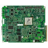
... General Information The MSC8156 application development system (MSC8156ADS complete debugging environment intended for engineers developing applications for the MSC8156 family and MSC8256 family of Freescale digital signal processors (DSPs). The MSC8156 and MSC8256 devices are highly integrated DSP processors that contains six StarCore SC3850 DSP subsystems (48 GMACS at 1 GHz) ...
Page 6
... TD-SCDMA, 3G-LTE, and WiMAX applications. The MSC8256 DSP family targets high-performance medical, aerospace and defense, and advanced test and measurement markets. The MSC8156ADS is intended to serve as a platform for software and hardware development in the MSC8156 DSP and MSC8256 DSP family environment. On-board resources and the associated ...
Page 7
... Stand-Alone Mode. The MSC8156ADS can run in a stand-alone mode like other application development systems, with direct connections to debuggers, power supply, and other external connections. AMC Mode. The MSC8156ADS is inserted in a standard MicroTCA backplane that allows testing of the high-speed serial RapidIO and PCI Express ports against other platforms. By using a proprietary B2B adaptor card, the MSC8156 can work with a second MSC8156 device on an additional ADS board ...
Page 8
... LD14 indicate power system status. Any failure causes to nPRST signal be low continuously. Push Buttons — Main Power-On-Reset (SW8) — Hard Reset (SW9) — Soft Reset (SW11) — NMI (SW10) — Scroll (SW12) to select display mode 1-4 2.5 V for I/O; and 3.3 V for onboard peripherals. ; MSC8156ADS Reference Manual, Rev. 2.1 Freescale Semiconductor ...
Page 9
... C SPI UART JTAG MII DDR-2 SODIMM DDR3-64 800M non-ECC FPGA SPI BOOT EEPROM1 FLASH BOOT Figure 1-2. ADS Block Diagram MSC8156ADS Reference Manual, Rev. 2.1 MSC8156ADS Block Diagram AMC 1 PORT0 SGMII switch PORT2 GE1,2:SGMIIx2 Differential PORT4-7 Signal Mux PORT8-11 3.3 V 2.5 V ...
Page 10
... On-Chip Emulation Port PC IBM-compatible Personal Computer PCIe Experess Peripheral Components Interconnect PHY Physical Layer POL Point-of-Load DC-DC converter PS, PSU Power Supply Unit RGMII Reduced Gigabit Media Independent Interface RCW(L,H) Reset Configuration Word (Low/High) 1-6 MSC8156ADS Reference Manual, Rev. 2.1 Freescale Semiconductor ...
Page 11
... Freescale provides the following documentation with this kit: MSC8156ADS Hardware Getting Started Guide MSC8156ADS Reference Manual MSC8156ADS Using Code Warrior™ and MSC8156ADS Kit Configuration Guide Specific device documentation for MSC8154, MSC8156, MSC8251, MSC8252, MSC8254, and MSC8256 can be obtained from the Freescale website (www.freescale.com), including the device technical data sheets and reference manuals ...
Page 12
... This interface uses a 2.5 V source and is not compatible with a 3.3 V interface. 1x/4x serial RapidIO endpoint operates at 1.25, 2.5, or 3.125 Gbaud and complies with Specification 1.2. 1x/2x/4x PCI Express endpoint operates at 2.5 Gbaud and complies with Specification 1.0. SGMII at 1.25 GBaud. MSC8156ADS Reference Manual, Rev. 2.1 Specifications Freescale Semiconductor ...
Page 13
... SerDes lines have DC blocking capacitors 0.1 µF. Differential pairs are routed with 100 Ω impedance. Freescale Semiconductor 0.1uF dif dif SGMII Switch dif dif 0.1uF dif dif multiplex dif dif dif SEL1 SEL2 dif dif dif dif Figure 2-1. SerDes Connection Scheme MSC8156ADS Reference Manual, Rev. 2.1 AMC Edge connector 0.1uF P0 P2 P10 P11 2-1 ...
Page 14
... SGMII P5 RGMII P2 PHY2 Rn “0xA” Diff Mux RJ45 Figure 2-2. ADS Gigabit Ethernet Links MSC8156ADS Reference Manual, Rev. 2.1 2xPort x (2xSGMII) 2xSerDes Port2 SSW Port 0 AMC Port 10 SSW Port 1 AMC Port 11 AMC Port 6 AMC Port 6 AMC Port 7 AMC Port 7 ...
Page 15
... The Management Interface bus accesses Switch internal registers or an external PHY. MDC buffers isolate MDC_DSP signals upon SRESET assertion. This enables the FPGA MII controller to act as Master on the Management Interface and configure GETH PHYs in RGMII mode. Freescale Semiconductor MSC8156ADS Reference Manual, Rev. 2.1 Gigabit Ethernet Ports bit SGMIIRST — ...
Page 16
... Switch nSGMII_Mode1,2 Table 2-2. MI Configuration Backplane Path Mode MSC815x-> Copper MSC815x-> AMC MSC8156-> Copper MSC815x-> AMC or MSC815x-> Copper MSC8156ADS Reference Manual, Rev. 2.1 88E1111 RMII phy 88E1111 phy Interconnection MSC815x->88E1111 or if RGMII switch presents 7380->88E1111 a MSC815x->88E6182 ->88E1111 a MSC815x-> ...
Page 17
... COP->RGMII 88E1111 88E1111 SerDes->RGMII 88E1111 FPGA MII MSC815x MSC815x RGMII port RGMII port Figure 2-4. Boot-over-ETH configuration MSC8156ADS Reference Manual, Rev. 2.1 Boot Over Ethernet Stand-Alone settings 1000Base-T per GE D. RJ-45 1,2 88E1111 FPGA 88E1111 COP->SerDes MII 88E6182 ...
Page 18
... Functional Description 2.6 DDR3-to-DDR2 Interposer The interposer is not part of MSC8156ADS Bill-of-material. It may be used for DDR-2 port validation in DDR2 configuration mode. The interposer is taken from MPC8569MDS project. 2.7 SPI Flash The M25P64 Mbit ( Serial Flash produced by ST. The Serial SPI Flash is used as indirect boot memory for MSC8156 for large-size code (> ...
Page 19
... TDM operations should only be used on the board when the RGMII PHYs are in isolation mode (see 2.2, Gigabit Ethernet Ports). Otherwise, the PHY Rx drivers can distort the appropriate TDM signals. The 125 MHz GETH input clock buffer is disabled when TDM mode is selected for both GE/TDM ports. Freescale Semiconductor MSC8156ADS Reference Manual, Rev. 2.1 E1/T1 Framer 2-7 ...
Page 20
... C Bus EN SPD MBOOT DDR2 Header 2 Figure 2- Bus Peripherals 2 C bus Master and I C Slave Controllers 2 C slaves on the bus. The SPD EEPROM on the DDR Module MSC8156ADS Reference Manual, Rev. 2.1 Thermal Sensor* 0x28 0x4C Header 0x51 0x52 SPD DDR3 Freescale Semiconductor ...
Page 21
... C Boot EEPROM programming prior MSC8156 first run is simple way 2 C EEPROM gets address 0x56 for bypass when boot. See below on FPGA EEPROM_ADDR nEEPROM_ADDR Big EEPROM2 RCW_SRC = ‘001’ RCW_SRC = ‘010’ Figure 2- EEPROM Select MSC8156ADS Reference Manual, Rev. 2 Small EEPROM1 Bus 2-9 ...
Page 22
... Because the MSC8156 uses 2.5 V for the I/O interfacxe, SPI bus level buffers are required to interface with 3.3 V SPI devices. 2- SPI BOOT FLASH SPI Bus OPT RGMII SGMII Switch Switch EEPROM Figure 2-8. SPI Bus Peripherals MSC8156ADS Reference Manual, Rev. 2.1 E1/T1 CLOCK E1/T1 Framer Synth. Framer Freescale Semiconductor ...
Page 23
... JTAG chain operation. See Table 2-3 for the different JTAG chain configurations The DUT is first in the JTAG chain. Freescale Semiconductor Type-B USB eUTAP con M U 14-pin Figure 2-9. ADS JTAG Multiplexer MSC8156ADS Reference Manual, Rev. 2.1 JTAG Debug Interface J1000 FPGA ISP MSC815x BCSR CTRL MUXP TAP CTRL JTAG ...
Page 24
... FPGA with the Lattice programming tool at any time. The programming mode can be forced by the appropriate setting of the 3-pin JP1000 PRG jumper; see Table 2-4. 2-12 AMC_X_Over Table 2-3. JTAG Port’ Order in Chain MSC8156 TAP_ctrl, MSC8156 a (TAP_ctrl + MSC8156)_0 MSC8156ADS Reference Manual, Rev. 2.1 MSC8156ADS_1 DSP JP1 Order in Chain b , (TAP_ctrl + MSC8156)_1 Freescale Semiconductor ...
Page 25
... NC 5 GND DB-9 DTR—Data Terminal Ready (O)—NC TXD—Transmit Data (O) RXD—Receive Data (I) DSR—Data Set Ready (I)—NC CTS—Clear To Send (I)—NC RTS—Request To Send (O)—NC MSC8156ADS Reference Manual, Rev. 2.1 RS-232 Port Setting CLOSE 1-2 CLOSE 2-3 OPEN 2-13 ...
Page 26
... HRST “SIG1” SRST “SIG2” “SIG3” nPRST_out PU nPRST PU nHRST PU nSRST SRST Figure 2-12. ADS Reset Scheme MSC8156ADS Reference Manual, Rev. 2.1 Power Supply PG PRST Voltage Super- visor MSC815x PORESET HRESET SRESET HRST Freescale Semiconductor ...
Page 27
... DIP-switches. At the second time interval the data is driven to the MSC8156. Only RCW_SRC three bits are driven the rest Word configuration DIP-switches don’t care. FPGA BCSR Reg. Array Volt PRST Monitor HRST SRST EEPROM MSC8156ADS Reference Manual, Rev. 2.1 Reset Operation and Configuration Description 1 2-15 ...
Page 28
... Functional Description These initial values are defined by DIP-Switches, latched in FPGA BCSR registers during PORESET and driven towards the appropriate MSC8156 pins until SRESET is negated. The MSC8156ADS preferable default setting is RCW_SRC = ‘000’ allowing control entire RCW bits array loaded from the BCSR implemented in FPGA ...
Page 29
... HCSL SR_REF_CLK1 SR_REF_CLK1 100,125 MHz SerDes2 100OHM HCSL SR_REF_CLK2 multiplex SR_REF_CLK2 2:1 100OHM Figure 2-14. MSC8156 Clock Scheme MSC8156ADS Reference Manual, Rev. 2.1 Clock Options CLKOUT CLKOUT TST CLK1 SR_TST_CLK1 SR_TST_CLK1 TST CLK1 TST CLK2 SR_TST_CLK2 SR_TST_CLK2 TST CLK2 from AMC ...
Page 30
... Clock Synth 2-dig shift Display register 14-segment 2-18 eUTAP AMC OnCE JTAG multiplex TAP ctrl file Cross Matrix Boot Seq IIB bus Figure 2-15. FPGA Block Diagram MSC8156ADS Reference Manual, Rev. 2.1 RGMII Phy MII Config Master Slave SPI ctrl Freescale Semiconductor ...
Page 31
... R/W R/W EEPROM,PM, Configuration Temp Sensor Programming R/W - R/W R/W Configuration master and I C slave. The I MSC8156ADS Reference Manual, Rev. 2.1 Programming Logic (FPGA) 2 SPI C ’011’ ’100’ R/W - R/W C Master is controlled from internal 2 C bus. MII R/W - R/W ...
Page 32
... BCSR_ADDR: five bits refer to 32-BCSR registers. 2-20 2 Table 2- Master Registers PRER[7:0] PRER[15:8] DIN[7: DOUT[7:0] READ WRITE ACK 2 C serial clock bus operation bus standard: MSC8156ADS Reference Manual, Rev. 2 Att Default R,W R,W R/W 0 TIP IRQ_FLAG R IACK R Freescale Semiconductor 0xff 0xff ...
Page 33
... C slave, and MICO32 may program it. Table 2-9 gives a Table 2-9. MII Controller Registers CLKDIV[6: PHYADDR[4:0] 0 RGADDR[4:0] TXD[7:0] TXD[15:8] RXD[7:0] RXD[15: All Data is ready to send via MII when high. — MSC8156ADS Reference Manual, Rev. 2.1 Programming Logic (FPGA Att R, W WCTRLDA RSTAT BUSY ...
Page 34
... Table 2-10. SPI Master Registers CHAR_LEN[5:0] ASS RSRV LSB DIV5 DIV4 DIV3 EEPROM FLASH RGMII_phy2 ield specifies how many bits are transmitted in one transfer. f MSC8156ADS Reference Manual, Rev. 2 Att W R R,W Tx_NEG Rx_NEG GO_BSY R/W DIV2 DIV1 DIV0 R/W RGMII_phy1 ...
Page 35
... MSC8156ADS Reference Manual, Rev. 2.1 Programming Logic (FPGA slave, MII and SPI modules. When 3-d byte 4-d byte - - Mask of read value Expected masked value - - <MSB dest. address> ...
Page 36
... DMA validation module — BCSR provides h/w write protection for serial SPI FLASH and I Logic to prevent signals contention. Internal controllers: JTAG and I 2-24 Figure 2-16. LED Display Serial Interface optional master/slave to expand board control functions. MSC8156ADS Reference Manual, Rev. 2 EEPROMs parts. Freescale Semiconductor ...
Page 37
... SERDES2 Protocol. Five bits S2P[4:0] choose the SerDes2 protocol according to Table 2-13 1. This feature is available starting with the ADS rev Pilot Freescale Semiconductor actually recognizes I C CLK triggering. — Function MSC8156ADS Reference Manual, Rev. 2.1 Programming Logic (FPGA) DEF ATT. on PRST SW3.2,3 R,W 0 R,W SW3.1, R,W SW4 ...
Page 38
... PEX 1x, RapidIO 1x @ 2.5GHz 11 PEX 1x 12 RapidIO 1x @ 1.25GHz 13 RapidIO 1x @ 2.5GHz 14 RIO 1x @ 2.5GHz, SGMII2 15 Reserved 16 PEX 2x, SGMII2 17 PEX 2x/RIO 1x 1.25 GHz 18 PEX 2x/RIO 1x 2.5 GHz 19 PEX 2x 1A-1F Reserved 2-26 Table 2-13. SerDes Port 2 Protocol (S2P) Protocol MSC8156ADS Reference Manual, Rev. 2.1 Freescale Semiconductor ...
Page 39
... Reserved RCW Low bits Not in use. 7 RSRVL8 Reserved RCW Low bit 8. Not in use. Freescale Semiconductor Function Table 2-15. SerDes Port 1 Protocol (S1P) Protocol Function MSC8156ADS Reference Manual, Rev. 2.1 Programming Logic (FPGA) DEF ATT. SW4.4-1 R,W ‘00’ R,W SW7.7 R,W SW7 ...
Page 40
... Serial RapidIO 1 without I 2 Serial RapidIO 1 with I 3 SPI 4 RGMII1 without I 5 SGMII1 without I 6 RGMII1 with I 7 SGMII1 with I MSC8156ADS Reference Manual, Rev. 2.1 DEF on PRST “0” ‘0’ SW7.6-1 DEF on PRST — normal operation. SW6.5 SW6.4 SW6.3 SW6.2 SW6 ...
Page 41
... Table 2-19. Boot Port Select (BPRT) BPRT[3:0] Value (HEX) 8 RGMII2 without I 9 SGMII2 without I 0xA RGMII2 with I 0xB SGMII2 with I 0xC-0xF — Function — Boot Slave. Function MSC8156ADS Reference Manual, Rev. 2.1 Programming Logic (FPGA) Description DEF on PRST SW1.5 SW1.4 SW1.3 SW1.2 0 ...
Page 42
... GPIO23 as the SPI select signal for SPI Flash during boot over SPI bus. A high provide boot operation. 2-30 Function Function — the type is small. Table 2-23. BCSR8 CTRL1 (Offset 8) Function MSC8156ADS Reference Manual, Rev. 2.1 DEF on ATT PRST SW2.7 R,W SW2.6 R,W SW2.5 R,W SW2 ...
Page 43
... Reset to DDR2,3 Modules. When low the DDR modules stay in reset. When high the DDR Modules function normally. 7 RSRV9 Not Implemented. Freescale Semiconductor Table 2-23. BCSR8 CTRL1 (Offset 8) Function Function MSC8156ADS Reference Manual, Rev. 2.1 Programming Logic (FPGA) DEF on ATT. PRST ‘1’ R,W ‘0’ R,W SW2.6 & ...
Page 44
... RGMII. The bits state together with BPL define Table 2-26. SERDES Multiplex Select SEL1(SW5.2), S1P(hex) SEL2(SW5.3) 5-8,A,B,E 1-4,9,10 MSC8156ADS Reference Manual, Rev. 2.1 DEF on PRST Defines S1P, S2P settings ‘1’ for pure PCI Express mode (SerDes Port 2 is configured for PCI ...
Page 45
... Green LED is illuminated when SIGNAL0 is low Red LED is illuminated when SIGNAL1 is low or Green LED is illuminated when SIGNAL2 is low Green LED is illuminated when SIGNAL3 is low MSC8156ADS Reference Manual, Rev. 2.1 Programming Logic (FPGA) PHY Mode SerDes-to-COP RGMII-to-SGMII SerDes-to-COP RGMII-to-COP DEF on PRST ATT. ...
Page 46
... Table 2-31. BCSR13 Description Miscellaneous Function 3 (Offset 0xD) BIT MNEMONIC 0 PRST Power-on-Reset. Writing low generates a PORESET pulse for MSC8156ADS to reconfigure it. Read out the nHRTS signal level. 1 SRST Soft Reset. Low asserts MSC8156 Soft Reset. When high, the MSC8144 operates normally. Read out the nSRTS signal level. 2-4 TDMDIV TDM Clock Divider ...
Page 47
... EE1 Pin. MSC8156 Debug Acknowledge signal. High value means MSC8156 stands in debug. When this bit is low the chip is running 7 RSRV17 Not Implemented. Freescale Semiconductor Function Function Function MSC8156ADS Reference Manual, Rev. 2.1 Programming Logic (FPGA) DEF on ATT. PRST ‘0’ R ‘1’ ...
Page 48
... DOT1U Bit of dot LED, digit 1. High is on. 1-7 SEG1U Indicated symbol in ASCII in User’s Mode. 2-36 Function Function Function Function MSC8156ADS Reference Manual, Rev. 2.1 DEF on ATT. PRST ‘1’ after reset R,W ‘0’ after reset R,W ‘111111’ - ATT. ...
Page 49
... The BCSR27 Register is a status register (read only). The BCSR27 fields are described below in Table 2-43. Table 2-43. BCSR27 Time Stamp 1 (Offset 0x1B) BIT MNEMONIC 0-7 TIMED Firmware Creation Day. Freescale Semiconductor Function Function Function Function MSC8156ADS Reference Manual, Rev. 2.1 Programming Logic (FPGA) ATT. R/W R/W Read At Calculated Read At Calculated Read At Programmed 2-37 ...
Page 50
... SubREV BCSR Sub Revision. Four additional bits revision coding. See Table 2-49 REV Value 2-38 Function Function Function Function Table 2-48. BCSR Rev Coding MSC8156ADS Reference Manual, Rev. 2.1 Read At Programmed Read At Programmed Read At Programmed Read At Programmed value Programmed value Board PCB rev ...
Page 51
... Freescale Semiconductor Table 2-49. BCSR Rev Coding Regular Board Board Bring-Up Version (with RGMII switch) Table 2-50. Map of Test Registers TR6[1] TR4[6:4] TR3[7:4] Function MSC8156ADS Reference Manual, Rev. 2.1 Programming Logic (FPGA) Board Assembly TR1[6], TR16[5:0] TR1[0:1] DEF on PRST ‘000’ ...
Page 52
... ZM308G are programmable via the I development and service. MSC8156 Power-UP sequence is programmed into the Power Manager device’s non-volatile memory. Figure 2-17 shows power distribution. 2- bus and can be changed by a user at any time during product MSC8156ADS Reference Manual, Rev. 2.1 Freescale Semiconductor ...
Page 53
... Figure 2-17. Power Distribution Scheme 2 C master controller adjusts the core power supply to the J2002 1 Jumpers 1,2 ON J2003 OFF 1.0 V Power Rail J2005 MSC8156ADS Reference Manual, Rev. 2.1 Power Supply System MC34716EP MC34716EP DDR-2 DDR-1 DDR2/DDR3 DDR2 Memory Memory 1.8 V 1.5 V/1 ...
Page 54
... SXC. After the 1.0 V supplies rise to 90% of their nominal value, the other DSP 2.5 V I/O supply rise. The Power-One Power Manager program setting provides the required power-up sequence. 2.18 Separate LEDs MSC8156ADS LEDs are described in Table 2-52. Ref. Name Color 1G Green ...
Page 55
... SPI: SPI serial flash — SRIO: Serial RapidIO port over AMC edge connector — RGMII1 or RGMII2: Boot from appropriate Ethernet RGMII port. — SGMII1 or SGMII2: Boot from appropriate Ethernet SGMII port. Freescale Semiconductor MSC8156ADS Reference Manual, Rev. 2.1 Two-Digit LED Display 2-43 ...
Page 56
... Functional Description 2.20 Push-Buttons Table 2-53 below describes the push-button functionality. Table 2-53. The MSC8156ADS Push Buttons Name and Description SW11 Soft Reset SW9 Hard Reset SW8 Power-on-Reset SW10 NMI (Abort) SW12 Scroll 2-44 Depiction Pressing button SW11results in a Soft Reset for the MSC8156 ...
Page 57
... Jumpers MSC8156ADS jumpers settings are described in Table 2-54. Jumper Name AMC JTAG expansion: • When CLOSED. The JTAG chain expands over AMC-X-Over card. GA value define order in JP1 AMC EXP • When OPEN. No JTAG chain outside the board. Default setting: OPEN Power-ON-Reset: • ...
Page 58
... Figure 2-19. MSC8156 Solderless Socket with Heatsink and Fan The MSC8156 socket is a solderless type. The socket vendor is Tyco.Typical socket is shown on Figure 2-19. A fan assembled on top of the heat sink improves thermal parameters. The socket can dissipate at least power. 2-46 MSC8156ADS Reference Manual, Rev. 2.1 Freescale Semiconductor ...
Page 59
... Expansion Options The MSC8156ADS has two options for expansion: a connection for a PTMC expansion card, and an AMC edge connector. Modules for these connections are supplied by third-party vendors, not Freescale Semiconductor. The PTMC expansion connection (with appropriate third-party card) allows expanded Ethernet and video capabilities and can serve as a verification tool ...
Page 60
... GPIO GND - GND - GPIO25 GPIO GPIO26 GPIO GPIO27 GPIO GPIO30 GPIO - - - - GPIO31 GPIO nNMI_OUT Interrupt GND - GND - - - nINT_OUT Interrupt - - GND - - - - - - - - - GND - - - MSC8156ADS Reference Manual, Rev. 2.1 Comment/Power 2.5 V 2 2.5 V 2.5 V 2.5 V 2.5 V 2.5 V 2.5 V 2 Freescale Semiconductor ...
Page 61
... GND - GND - UTXD/GPIO29 UART GPIO1 GPIO URXD/GPIO28 UART GPIO2 GPIO GND - - - GPIO3 GPIO - - GPIO4 GPIO GPIO5 GPIO GND - MSC8156ADS Reference Manual, Rev. 2.1 PMC Expansion Connection Comment/Power - - - - - - - - - +2 2.5 V 2.5 V 2.5 V Set on-board RS-232 transc. disable for GPIO mode/ 2.5 V 2.5 V PTMC ID Pull-Down 2 ...
Page 62
... GND - TDM2TSN TDM2 TDM3RCK TDM3 TDM3TSN TDM3 TDM3RDT TDM3 GND - - - TDM3TCK TDM3 - - TDM2TCK TDM2 MSC8156ADS Reference Manual, Rev. 2.1 Comment/Power - b Main TDM SYNC / 3 Add. SYNC1 / 3.3 V PTMC ID Pull-Down 2.5 V Special Purpose GND 2.5 V Main TDM CLOCK/ 3.3 V 2 ...
Page 63
... TDM1RSN TDM1 TDM0RCK TDM0 TDM0TDT TDM0 TDM0RDT TDM0 GND - GND - TDM0RSN TDM0 MSC8156ADS Reference Manual, Rev. 2.1 PMC Expansion Connection Comment/Power f Secondary Master Clock / 3.3 V Any Mode/ 3.3 V Any Mode/ 3.3 V Any Mode/ 3.3 V Any Mode/ 3.3 V Any Mode/ 3.3 V Any Mode/ 3 ...
Page 64
... AMC in ATCA Environment The card may be plugged into AMC carrier via a 170 pin edge B+ connector. That allows MSC8156ADS to connect to a TUNDRA device on the TUNDRA backplane, or any other ATCA system. Using proprietary AMC back-to- back adaptor card two MSC8156ADS boards may be tested together. ...
Page 65
... Fxdata10(TDM2RCK) Fxdata11(TDM2TDT) Fxdata12(TDM3RDT) Fxdata13(TDM3RSN) Fxdata14(TDM3RCK) Fxdata15(TDM3TDT) - Fxsync (TDM0TSN) a Fxclk (TDM0TCK) TCKamc TMSamc nTRSTamc TDOamc TDIamc MSC8156ADS Reference Manual, Rev. 2.1 AMC in ATCA Environment ATCA Carrier Board Signal Serial RapidIO 1/4x ST_D00 ST_D01 ST_D02 ST_D03 ST_D04 ST_D05 ST_D06 ST_D07 ST_D08 ST_D09 ST_D10 ...
Page 66
... Expansion Options 3-8 MSC8156ADS Reference Manual, Rev. 2.1 Freescale Semiconductor ...
Page 67
... Freescale Semiconductor 2 C bus with an initialized FPGAs I C bus options become unavailable such as boot over I MSC8156ADS Reference Manual, Rev. 2 Master Controller DDR SPD read, A-1 ...
Page 68
... A-2 // Phy RGMII mode - add delay for clock // Phy RGMII mode - add delay for clock // Two phys are in RGMII mode - add delay for clock // Need to insert phys into isolate mode because TDM mode 0x09 MSC8156ADS Reference Manual, Rev. 2.1 Freescale Semiconductor ...
Page 69
... Disable to Clock Buffer WR BCSR,9 0x7b // Enable TDM Framer JMP C // Read die temperature sensor 5: WR I2CM,2 0x80 WR I2CM,0 0x3f WR I2CM,1 0x00 // Configure the sensor Freescale Semiconductor // Enable to I2C Master Controller // // Set I2C speed 100kHz MSC8156ADS Reference Manual, Rev. 2.1 Boot Sequencer Assembler File A-3 ...
Page 70
... I2CM,4 0x90 // Command to write RD I2CM,4 0x41 0x41 // Wait to finish WR I2CM,4 0x68 // Command to write RD I2CM,4 0x81 0x81 // Wait to finish RTA I2CM,3 // Read temperature value into accumulator A-4 // Enable to I2C Master Controller // // Set I2C speed 100kHz MSC8156ADS Reference Manual, Rev. 2.1 Freescale Semiconductor ...
Page 71
... WR I2CM,2 0x00 // Disable to I2C Master Controller WFA BCSR,21 END // End of boot Freescale Semiconductor // Write to the User's Display Register MSC8156ADS Reference Manual, Rev. 2.1 Boot Sequencer Assembler File A-5 ...
Page 72
... A-6 MSC8156ADS Reference Manual, Rev. 2.1 Freescale Semiconductor ...