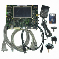
AT91SAM9G45-EKES Atmel, AT91SAM9G45-EKES Datasheet - Page 2

AT91SAM9G45-EKES
Manufacturer Part Number
AT91SAM9G45-EKES
Description
KIT EVAL FOR AT91SAM9G45
Manufacturer
Atmel
Series
AT91SAM Smart ARMr
Type
MCUr
Datasheets
1.AT91SAM9G45-EKES.pdf
(56 pages)
2.AT91SAM9G45-EKES.pdf
(1218 pages)
3.AT91SAM9G45-EKES.pdf
(66 pages)
Specifications of AT91SAM9G45-EKES
Contents
Board
Processor To Be Evaluated
SAM9G45
Data Bus Width
32 bit
Interface Type
I2C, SPI, UART
Maximum Operating Temperature
+ 50 C
Minimum Operating Temperature
- 10 C
Operating Supply Voltage
1.8 V to 3.3 V
For Use With/related Products
AT91SAM9G45
Lead Free Status / RoHS Status
Lead free / RoHS Compliant
Other names
Q4626953
Section 1
Introduction .................................................................................................................1-1
Section 2
Kit Contents ................................................................................................................2-1
Section 3
Power Up ....................................................................................................................3-1
Section 4
Board Description .......................................................................................................4-1
AT91SAM9G45-EKES User Guide
1.1
1.2
2.1
2.2
2.3
3.1
3.2
3.3
3.4
3.5
4.1
4.2
Scope ................................................................................................................................. 1-1
Applicable Documents ....................................................................................................... 1-2
Deliverables ....................................................................................................................... 2-1
Evaluation Board Specifications......................................................................................... 2-2
Electrostatic Warning ......................................................................................................... 2-2
Power Up the Board........................................................................................................... 3-1
Battery................................................................................................................................ 3-1
DevStart ............................................................................................................................. 3-1
Recovery Procedure .......................................................................................................... 3-1
Sample Code and Technical Support ................................................................................ 3-2
Equipment on the Board .................................................................................................... 4-1
Hardware Layout and Configuration .................................................................................. 4-3
4.1.1
4.1.2
4.1.3
4.1.4
4.2.1
4.2.2
4.2.3
4.2.4
4.2.5
4.2.6
4.2.7
4.2.8
4.2.9
4.2.10 Serial Peripheral Interface Controller (SPI) ....................................................... 4-17
4.2.11 Two Wire Interface (TWI)................................................................................... 4-18
4.2.12 SD/MMC Interface ............................................................................................. 4-18
4.2.13 TFT LCD with Touch Panel ............................................................................... 4-20
4.2.14 Push Buttons ..................................................................................................... 4-22
Interfaces ............................................................................................................. 4-1
Board Interface Connection ................................................................................. 4-2
Push Button Switches .......................................................................................... 4-2
Display LCD and LEDs ........................................................................................ 4-3
Processor............................................................................................................. 4-3
Clock Circuitry...................................................................................................... 4-3
Reset Circuitry ..................................................................................................... 4-4
Memory ................................................................................................................ 4-4
Power Supplies .................................................................................................... 4-7
Debug Interface ................................................................................................... 4-9
Audio Stereo Interface ....................................................................................... 4-14
TV-Out Extension .............................................................................................. 4-16
Software Controlled LEDs ................................................................................. 4-16
6481B–ATARM–27-Nov-09
1-i


