DV164121 Microchip Technology, DV164121 Datasheet - Page 38
DV164121
Manufacturer Part Number
DV164121
Description
KIT PICKIT 2 DEBUG EXPRESS
Manufacturer
Microchip Technology
Series
PICkit™ 2r
Type
Microcontrollerr
Specifications of DV164121
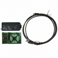
Contents
Board, PICkit™ 2 Programmer, Cable, CD
Processor To Be Evaluated
PIC family
Data Bus Width
8 bit, 16 bit, 32 bit
Lead Free Status / RoHS Status
Lead free / RoHS Compliant
For Use With/related Products
PIC Micro® MCU
Lead Free Status / Rohs Status
Lead free / RoHS Compliant
Available stocks
Company
Part Number
Manufacturer
Quantity
Price
Company:

Part Number:
DV164121
Manufacturer:
Microchip Technology
Quantity:
135
Company:
Part Number:
DV164121
Manufacturer:
MICROCHIP
Quantity:
12 000


DS51553E-page 34
4.4.4
PIC microcontroller devices that do not require an ICD Header and may be debugged
directly contain a DEBUG bit in the Configuration Word(s) that enables and disables
the debug mode on the PIC microcontroller.
This bit is automatically set appropriately by the MPLAB IDE when using PICkit 2
Debug Express and should not be specified in source code configuration settings.
Many 16-bit PIC microcontroller devices such as PIC24 and dsPIC33 families have
multiple ICSP programming and debugging port pins labeled PGC1/EMUC1 and
PGD1/EMUD1, PGC2/EMUC2 and PGD2/EMUD2, etc. While any ICSP port may be
used for programming, only one port is active at a time for debugging. The active EMU
port is set in the device Configuration bits. If the active port setting does not match the
EMU port to which the PICkit 2 is connected, the device will be unable to enter debug
mode. In the MPLAB IDE Configuration Bits dialog, these bits are usually referred to as
the “Comm Channel Select” bits.
4.4.5
The number of active breakpoints supported by PICkit 2 Debug Express depends on
the target device. Most Baseline and Mid-Range devices support 1 breakpoint, with
more breakpoints supported in some PIC18 and 16-bit devices.
The number of active breakpoints available for the current device in MPLAB IDE can
be seen by selecting Debugger>Breakpoints…. This will open a dialog (Figure 4-3)
showing any currently set breakpoints in Program Memory. The “Active Breakpoint
Limit:” text box shows how many total breakpoints are available for the current device.
The “Available Breakpoints:” text box shows how many breakpoints are currently
unused.
FIGURE 4-3:
Some PIC18 and 16-bit devices also support advanced breakpoints. Advanced break-
points allow breakpoints to be set in File Register memory, and will halt execution when
a specific File Register is read from or written to. This breakpoint may also be set so it
will only halt when a specific value is read from or written to a register. Additionally, a
The DEBUG configuration bit value should not be specified in source code Configura-
tion settings under normal conditions. Doing so may cause the bit to be asserted when
programming a device outside the debugger. This will cause the device to function
improperly or not all at in the application circuit.
Configuration Bits and Debug Express
Debug Express Breakpoints
BREAKPOINTS DIALOG FOR PIC16F887
CAUTION
© 2008 Microchip Technology Inc.
Related parts for DV164121
Image
Part Number
Description
Manufacturer
Datasheet
Request
R

Part Number:
Description:
Manufacturer:
Microchip Technology Inc.
Datasheet:
Part Number:
Description:
Manufacturer:
Microchip Technology Inc.
Datasheet:
Part Number:
Description:
Manufacturer:
Microchip Technology Inc.
Datasheet:
Part Number:
Description:
Manufacturer:
Microchip Technology Inc.
Datasheet:
Part Number:
Description:
Manufacturer:
Microchip Technology Inc.
Datasheet:
Part Number:
Description:
Manufacturer:
Microchip Technology Inc.
Datasheet:
Part Number:
Description:
Manufacturer:
Microchip Technology Inc.
Datasheet:
Part Number:
Description:
Manufacturer:
Microchip Technology Inc.
Datasheet: