DV164121 Microchip Technology, DV164121 Datasheet - Page 48
DV164121
Manufacturer Part Number
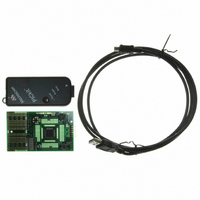
DV164121
Description
KIT PICKIT 2 DEBUG EXPRESS
Manufacturer
Microchip Technology
Series
PICkit™ 2r
Type
Microcontrollerr
Specifications of DV164121
Contents
Board, PICkit™ 2 Programmer, Cable, CD
Processor To Be Evaluated
PIC family
Data Bus Width
8 bit, 16 bit, 32 bit
Lead Free Status / RoHS Status
Lead free / RoHS Compliant
For Use With/related Products
PIC Micro® MCU
Lead Free Status / Rohs Status
Lead free / RoHS Compliant
Available stocks
Company
Part Number
Manufacturer
Quantity
Price
Company:

Part Number:
DV164121
Manufacturer:
Microchip Technology
Quantity:
135
Company:
Part Number:
DV164121
Manufacturer:
MICROCHIP
Quantity:
12 000


DS51553E-page 44
4.5.8
The PICkit 2 Debug Express executes the program code in either real-time (Run) or in
steps (Step Into, Step Over, Step Out, Animate.) Real-time execution occurs when you
select Run in MPLAB IDE. When the program is halted, either by Halt or at a
breakpoint, you can step through the code.
The following toolbar buttons can be used for quick access to commonly used debug
operations:
To run the demo code:
1. Double click on the 16F887Demo.asm file from the Project window or select
2. Select Debugger>Run or click Run.
3. Turn the potentiometer (RP1), located on the demo board, and observe the
If the program were working properly, the LEDs would rotate faster or slower depending
on in which direction the potentiometer is turned. However, a bug has been intentionally
placed in the code for debugging demonstration purposes. See
Section 4.5.9 “Debugging the PIC16F887 Debug Demo Code” for debugging
instructions.
4. Select Debugger>Halt or click Halt to stop the program execution. A green solid
5. Select Debugger>Reset>Processor Reset to reset the program. The arrow will
4.5.9
Any of the following issues can prevent the PIC16F887 Debug Demo program from
working properly:
1. The A/D converter value is not being written properly to the Delay routine.
2. The A/D converter is not enabled or has not been set to convert.
3. A typing error in the source code has caused the program to function improperly.
To explore the issue listed first, set a breakpoint at the line of code that writes the value
of the A/D result to the high-order Delay byte:
1. Place the cursor on the following line of code in the 16F887Demo.asm file:
2. Either right click on the line to display a drop-down menu and select
File>Open from the toolbar menu. The code will appear in a File window.
LEDs.
arrow will mark the line of code in the File window where the program halted.
disappear, meaning the device is Reset.
movwf Delay+1, as shown in Figure 4-19.
At this breakpoint, the program will stop once the A/D conversion has completed.
“Set Breakpoint” or double click on the line. A breakpoint symbol will appear next
to the line as the letter B in a solid red octagon, as shown in Figure 4-19.
Running the PIC16F887 Debug Demo
Debugging the PIC16F887 Debug Demo Code
Debugger Menu
Step Over
Step Into
Step Out
Animate
Reset
Run
Halt
Toolbar Buttons
© 2008 Microchip Technology Inc.
Related parts for DV164121
Image
Part Number
Description
Manufacturer
Datasheet
Request
R

Part Number:
Description:
Manufacturer:
Microchip Technology Inc.
Datasheet:
Part Number:
Description:
Manufacturer:
Microchip Technology Inc.
Datasheet:
Part Number:
Description:
Manufacturer:
Microchip Technology Inc.
Datasheet:
Part Number:
Description:
Manufacturer:
Microchip Technology Inc.
Datasheet:
Part Number:
Description:
Manufacturer:
Microchip Technology Inc.
Datasheet:
Part Number:
Description:
Manufacturer:
Microchip Technology Inc.
Datasheet:
Part Number:
Description:
Manufacturer:
Microchip Technology Inc.
Datasheet:
Part Number:
Description:
Manufacturer:
Microchip Technology Inc.
Datasheet: