DM300004-1 Microchip Technology, DM300004-1 Datasheet - Page 50
DM300004-1
Manufacturer Part Number
DM300004-1
Description
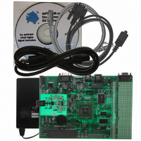
BOARD DEMO DSPICDEM.NET 1
Manufacturer
Microchip Technology
Series
dsPIC™r
Type
Microcontrollerr
Specifications of DM300004-1
Contents
*
Mcu Supported Families
DsPIC30F
Supported Devices
DsPIC30F6014
For Use With
PIC30F5013
Lead Free Status / RoHS Status
Lead free / RoHS Compliant
For Use With/related Products
FCC/JATE PSTN, Ethernet NIC
Lead Free Status / RoHS Status
na, Lead free / RoHS Compliant
Other names
DM300004-1R
DM300004-1R
DM300004-1R


PICDEM.net™ 1 and dsPICDEM.net 2 Connectivity Dev Board User’s Guide
3.9
DS51471A-page 46
DATA AND CONTROL FLOW
• Data Converter Interface – Interfaced to an external Si303x DAA/AFE chipset for
• INTx pins – Used for detecting switch S1-S3 inputs.
• PORTD pins, RD0-RD15 – Used to interface to 64Kx16 SRAM, 10-base T NIC
3.9.1
Table 3-1 provides more details on the power-up peripheral initialization sequence
illustrated in Figure 3-17.
TABLE 3-1:
3.9.2
Table 3-2 explains the step-by-step execution sequence of the Main Loop shown in
Figure 3-18
TABLE 3-2:
PSTN interface control and monitor.
and 2x16 LCD.
Seq
Seq.
10
11
1
2
3
4
5
6
7
8
9
1
2
3
4
5
Timer1
Timer2
Timer3
2x16 LCD
64Kx16 SRAM
10-base T NIC
UART1
Data Converter
External interrupt
SPI™ 1
12-bit ADC
Interface (DCI)
pins INT1-INT3
Check state of variable “hook_status”, which is modified in either INT1, INT2 and
INT3 Interrupt Service Routines.
12-bit ADC collects a sample each from the digital potentiometer RP1 and RP2 and
temperature sensor, U2.
Data obtained from ADC is converted to ASCII for display by UART and LCD.
LCD is updated with Potentiometer RP1 and RP2 values.
SPI 1 transmit RP1 and RP2 values to dual channel digital potentiometer. Monitor of
potentiometer output is via PW0 and PW1 test points on board.
Module or Board
Power-up Sequence
Main Loop Code Execution
Function
POWER-UP PERIPHERAL INITIALIZATION SEQUENCE
MAIN LOOP CODE EXECUTION SEQUENCE
Configured to count to 2.2 mS and reset.
Configured to count to 3.95 mS and reset.
Configured to count to 2.2 mS and reset.
Initialization of 2x16 character LCD, via PORTD pins
RD0-RD15.
Initialization and test of 64Kx16 SRAM, via PORTD pins
RD0-RD15. Testing is performed by writing and reading back
a specific incrementing pattern.
Initialization and test of 10-base T NIC, via PORTD pins
RD0-RD15. Testing is performed by performing internal
loop-back tests as supported by the NIC.
The transmitter is configured for interrupt-driven operation at
38400 baud.
Configured for Slave mode. Configured to communicate to the
Si303x DAA/AFE chipset operating in Master mode. Some
DAA/AFE self test routines are executed.
Configured to interrupt on the falling edge and used for
switches S1-S3, respectively.
Configured for communication with MCP42050 Dual Channel
Digital potentiometer.
Configured to continuously sample channels AN3
(temperature sensor U2), AN4 (RP1) and AN5 (RP2).
Program Task
Initialization Process
2004 Microchip Technology Inc.
Related parts for DM300004-1
Image
Part Number
Description
Manufacturer
Datasheet
Request
R

Part Number:
Description:
Manufacturer:
Microchip Technology Inc.
Datasheet:
Part Number:
Description:
Manufacturer:
Microchip Technology Inc.
Datasheet:
Part Number:
Description:
Manufacturer:
Microchip Technology Inc.
Datasheet:
Part Number:
Description:
Manufacturer:
Microchip Technology Inc.
Datasheet:
Part Number:
Description:
Manufacturer:
Microchip Technology Inc.
Datasheet:
Part Number:
Description:
Manufacturer:
Microchip Technology Inc.
Datasheet:
Part Number:
Description:
Manufacturer:
Microchip Technology Inc.
Datasheet:
Part Number:
Description:
Manufacturer:
Microchip Technology Inc.
Datasheet: