DM300004-1 Microchip Technology, DM300004-1 Datasheet - Page 51
DM300004-1
Manufacturer Part Number
DM300004-1
Description
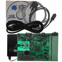
BOARD DEMO DSPICDEM.NET 1
Manufacturer
Microchip Technology
Series
dsPIC™r
Type
Microcontrollerr
Specifications of DM300004-1
Contents
*
Mcu Supported Families
DsPIC30F
Supported Devices
DsPIC30F6014
For Use With
PIC30F5013
Lead Free Status / RoHS Status
Lead free / RoHS Compliant
For Use With/related Products
FCC/JATE PSTN, Ethernet NIC
Lead Free Status / RoHS Status
na, Lead free / RoHS Compliant
Other names
DM300004-1R
DM300004-1R
DM300004-1R


2004 Microchip Technology Inc.
3.9.3
3.9.3.1
External interrupts INT1-INT3 are controlled by switches S1-S3 respectively.
Each switch is monitored by the respective Interrupt pin, INT1-INT3. For each switch
detected the variable “hook_status” is modified in the ISR. The variable “hook_status”
is then monitored in the main loop and based upon the variable state one of three
actions are taken.
3.9.3.2
The 12-bit module is configured to continually sample and convert channels AN3
(temperature sensor U2), AN4 (RP1) and AN5 (RP2). When all three signals have been
converted an ADC module based interrupt occurs and the ISR code simply saves off
the converted values to variables defined in data memory. Outside the interrupt this
“raw” data is converted to ASCII by a simple conversion routine and then used by the
UART and LCD display code modules.
3.9.3.3
Approximately every 200 mS, data is transmitted via the UART to the HyperTerminal
session window. The term “data” refers to the following:
• Analog data such as RP1 and RP2 voltages
• Temperature sensor data, U2
3.9.3.4
Timer1 is a 16-bit timer that uses the instruction cycle as its time-base. It is configured
to time out and generate an interrupt every 2.2 milliseconds. The Timer1 Interrupt
Service Routine (ISR) simply toggles LED1 and clears the associated interrupt flag.
3.9.3.5
Timer2 is a 16-bit timer that uses the instruction cycle as its time-base. It is configured
to time out and generate an interrupt every 3.95 milliseconds. The Timer2 Interrupt
Service Routine (ISR) increments a variable, tests bit 9 of this variable and if set toggles
LED2. If LED2 is toggled the ISR resets this same variable to zero. Finally the
associated interrupt flag is cleared.
3.9.3.6
Timer3 is a 16-bit timer that uses the instruction cycle as its time-base. It is configured
to time out and generate an interrupt every 2.2 milliseconds. The Timer3 Interrupt
Service Routine (ISR) increments a variable, tests bit 9 of this variable and if set toggles
LED3. If LED3 is toggled the ISR resets this same variable to zero. Finally the
associated interrupt flag is cleared.
Interrupts Used in the Demonstration Program
EXTERNAL INTERRUPTS TO MAIN ROUTINE
12-BIT ADC INTERRUPTS
UART TRANSMIT INTERRUPTS
TIMER1
TIMER2
TIMER3
Quick Start Program
DS51471A-page 47
Related parts for DM300004-1
Image
Part Number
Description
Manufacturer
Datasheet
Request
R

Part Number:
Description:
Manufacturer:
Microchip Technology Inc.
Datasheet:
Part Number:
Description:
Manufacturer:
Microchip Technology Inc.
Datasheet:
Part Number:
Description:
Manufacturer:
Microchip Technology Inc.
Datasheet:
Part Number:
Description:
Manufacturer:
Microchip Technology Inc.
Datasheet:
Part Number:
Description:
Manufacturer:
Microchip Technology Inc.
Datasheet:
Part Number:
Description:
Manufacturer:
Microchip Technology Inc.
Datasheet:
Part Number:
Description:
Manufacturer:
Microchip Technology Inc.
Datasheet:
Part Number:
Description:
Manufacturer:
Microchip Technology Inc.
Datasheet: