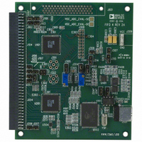
HSC-ADC-EVALA-DC Analog Devices Inc, HSC-ADC-EVALA-DC Datasheet - Page 20

HSC-ADC-EVALA-DC
Manufacturer Part Number
HSC-ADC-EVALA-DC
Description
KIT EVAL FOR DUAL ADC/CONV
Manufacturer
Analog Devices Inc
Specifications of HSC-ADC-EVALA-DC
Lead Free Status / RoHS Status
Contains lead / RoHS non-compliant
AN-905
DAC PATTERN GENERATOR INTERFACE
The DAC Pattern Generator Interface provides access to the
physical DPG board via a standard USB interface. This tool
handles all of the hardware interfacing and data formatting
issues that are required to move data from a software data set
(vector) to the hardware. Additional information on the DPG is
available at www.analog.com. Note that only one DPG should
be connected at any given time. When using the DPG along
with other USB devices in VisualAnalog, be sure to connect the
DPG first.
The DAC Pattern Generator Interface component requires
unsigned data that matches the resolution, bit alignment, and
data format of the DAC. When using VisualAnalog processed
data, the Output Formatter is required to format the data for
the DPG device in a numeric format and resolution that the
DAC expects. If this is not set properly, incorrect data sent to
the DAC results in erroneous performance. Consult the DAC
product data sheet to ensure that the output formatter is set
properly. For more information on setting up the Output
Formatter, see the Output Formatter section.
DAC PATTERN GENERATOR CONTROL FORM
Click Settings on the DAC Pattern Generator Interface to
open the DAC Pattern Generator Settings form. You can use
this form to adjust settings on the DPG and control playback of
patterns. The form consists of four tabs: Setup, Tuning, Debug,
and Tx Config.
Setup
Use the Setup tab to set the DPG in the desired operating mode
and to control data playback settings.
Configuration allows you to set the DPG in the desired
operating mode.
Figure 42. DAC Pattern Generator Interface
Figure 43. Setup Tab
Rev. 0 | Page 20 of 40
Table 1. DPG Operating Modes
Port
P1: LVDS Serialized
P2: LVDS Direct
P3: LVCMOS
Data Playback controls playback settings and start/stop
playback and becomes active when the control is fully
configured and data is loaded.
Table 2. Data Playback Controls
Control
Start Offset
Play Length
Mode
Count
State
Indicator
Play/Stop
Button
Tuning
The Tuning tab holds the controls for data and clock tuning.
Serialized LVDS Tuning holds the controls related to tuning
for the serialized LVDS port.
Description
Specifies the start location of the playback with
respect to the first vector data value. Must be a
multiple of 256 bits (32 bytes).
Specifies the data length to playback. Must be a
multiple of 256 bits (32 bytes).
Sets the desired playback mode as follows:
Loop - File content is played and repeated until
the session is stopped.
Count - File content is played and repeated the
number of times specified in the Count field.
Once - File content is played only once on the
output port.
Specifies the playback count. Only active when
the count mode is selected.
Provides general playback status information to
the user.
Starts/stops a playback session. A vector must be
loaded.
Figure 44. Tuning Tab
Mode
Clock aligned
Clock centered
SDR
DDR: centered
DDR: coincident
Single port
Dual port


