HDJD-JD05 Avago Technologies US Inc., HDJD-JD05 Datasheet - Page 8
HDJD-JD05
Manufacturer Part Number
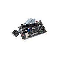
HDJD-JD05
Description
KIT DEV RGB COLOR SENSOR 20-QFN
Manufacturer
Avago Technologies US Inc.
Specifications of HDJD-JD05
Sensor Type
Light, Color Sensor
Sensing Range
RGB
Interface
2-Wire Serial
Voltage - Supply
2.5 V ~ 3.6 V
Embedded
No
Utilized Ic / Part
ADJD-S313-QR999
For Use With/related Products
ADJD-S313-QR999
Lead Free Status / RoHS Status
Not applicable / Not applicable


Serial Interface Reference
Description
The programming interface to the ADJD-S313 is a
2-wire serial bus. The bus consists of a serial clock
(SCL) and a serial data (SDA) line. The SDA line is
bi-directional on ADJD-S313 and must be
connected through a pull-up resistor to the positive
power supply. When the bus is free, both lines are
HIGH.
The 2-wire serial bus on ADJD-S313 requires one
device to act as a master while all other devices
must be slaves. A master is a device that initiates a
data transfer on the bus, generates the clock signal
and terminates the data transfer while a device
addressed by the master is called a slave. Slaves
are identified by unique device addresses.
Both master and slave can act as a transmitter or a
receiver but the master controls the direction for
data transfer. A transmitter is a device that sends
data to the bus and a receiver is a device that
receives data from the bus.
The ADJD-S313 serial bus interface always operates
as a slave transceiver with a data transfer rate of
up to 100kbit/s.
Figure 1. START/STOP Condition
Figure 2. Data Bit Transfer
8
SDA
SCL
SDA
SCL
START condition
S
Data valid
Data change
START/STOP Condition
The master initiates and terminates all serial data
transfers. To begin a serial data transfer, the master
must send a unique signal to the bus called a START
condition. This is defined as a HIGH to LOW
transition on the SDA line while SCL is HIGH.
The master terminates the serial data transfer by
sending another unique signal to the bus called a
STOP condition. This is defined as a LOW to HIGH
transition on the SDA line while SCL is HIGH.
The bus is considered to be busy after a START (S)
condition. It will be considered free a certain time
after the STOP (P) condition. The bus stays busy if
a repeated START (Sr) is sent instead of a STOP
condition.
The START and repeated START conditions are
functionally identical.
Data Transfer
The master initiates data transfer after a START
condition. Data is transferred in bits with the master
generating one clock pulse for each bit sent. For a
data bit to be valid, the SDA data line must be
stable during the HIGH period of the SCL clock line.
Only during the LOW period of the SCL clock line
can the SDA data line change state to either HIGH
or LOW.
STOP condition
P
Related parts for HDJD-JD05
Image
Part Number
Description
Manufacturer
Datasheet
Request
R

Part Number:
Description:
KIT DEV RGB COLOR SENSOR 16-QFN
Manufacturer:
Avago Technologies US Inc.
Datasheet:

Part Number:
Description:
KIT DEV RGB COLOR SENSOR 16-QFN
Manufacturer:
Avago Technologies US Inc.
Datasheet:

Part Number:
Description:
KIT DEV RGB DCS 2.2X2.2
Manufacturer:
Avago Technologies US Inc.
Datasheet:

Part Number:
Description:
Optical Sensor
Manufacturer:
Avago Technologies US Inc.
Datasheet:
Part Number:
Description:
RGB COLOR CONTROLLER AND SENSOR
Manufacturer:
Avago Technologies US Inc.
Part Number:
Description:
Photodiodes Color Controller
Manufacturer:
Avago Technologies US Inc.

Part Number:
Description:
Optical Sensors - Board Mount RGB Color Sensor
Manufacturer:
Avago Technologies US Inc.

Part Number:
Description:
Optical Sensors - Board Mount RGB Color Sensor
Manufacturer:
Avago Technologies US Inc.

Part Number:
Description:
Optical Sensor Development Tools RGB CONTROLLER Development Kit
Manufacturer:
Avago Technologies US Inc.

Part Number:
Description:
Optical Sensor Development Tools RGB CONTROLLER Development Kit
Manufacturer:
Avago Technologies US Inc.

Part Number:
Description:
OPTOCOUPLER GATE DRV 2A 16-SOIC
Manufacturer:
Avago Technologies US Inc.
Datasheet:
Part Number:
Description:
OPTOCOUPLER 2CH 2.5A 16-SOIC
Manufacturer:
Avago Technologies US Inc.
Datasheet:

Part Number:
Description:
OPTOCOUPLER GATE DRV 0.4A 16SOIC
Manufacturer:
Avago Technologies US Inc.
Datasheet:

Part Number:
Description:
OPTOCOUPLER 2.0A 250KHZ 8-DIP
Manufacturer:
Avago Technologies US Inc.
Datasheet:

Part Number:
Description:
OPTOCOUPLER 2.0A 250KHZ GW 8-SMD
Manufacturer:
Avago Technologies US Inc.
Datasheet: