ZK-S12-B SofTec Microsystems SRL, ZK-S12-B Datasheet
ZK-S12-B
Specifications of ZK-S12-B


Related parts for ZK-S12-B


ZK-S12-B Summary of contents
Page 1
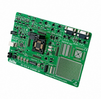
... User’s Manual 1. Introduction Overview The ZK-S12-B Starter Kit has been designed for the evaluation of the 80- pin QFP Freescale HCS12(X) family and the debugging of user applications. The ZK-S12-B Starter Kit can be used as a standalone application, via its built-in USB to BDM interface, or together with an external debugger through a BDM-compatible connection ...
Page 2
... DTE/DCE SEL”). The microcontroller’s RX and TX lines used by the RS-232 transceivers are shared with the LIN trasceivers’ RX and TX lines, respectively. Use the “RXDx SEL” and “TXDx SEL” jumpers in the “SERIAL ZK-S12-B User's Manual Page 2 ...
Page 3
... CAN bus. 12. A prototype area features both a standard, thru-hole area (for mounting traditional components) and a SMD area (for soldering SMD components). Additionally, all of the board’s supply lines ( VDD and GND lines) are provided The ZK-S12-B Starter Kit ZK-S12-B User's Manual Page 3 ...
Page 4
... Recommended Reading 2. Device Configuration Oscillator Configuration Thanks to the 80-pin QFP ZIF socket, the ZK-S12-B Starter Kit can support different devices, as detailed in the table below. All of the jumpers in the “MCU” section of the board must be set according to the specific microcontroller installed. Particular care must be taken in order to correctly set the oscillator configuration ...
Page 5
... CAN3 Reference Description/Pinout VRH SELECTION 1 2 1-2 (VDDA) VRH tied to VDDA (default) 3 2-3 (USER) VRH connected to the J103 connector ZK-S12-B User's Manual Clock “XCLKS#=0” “OSC SEL” “XCLKS#=0” Jumper Jumpers Jumper Not Installed “CLOCK” Installed Not Installed “CLOCK” ...
Page 6
... J204 LED ENABLE 1 Installed Not Installed ZK-S12-B User's Manual VRL tied to ground (default) VRL connected to the J104 connector The on-board RC PLL loop filter is selected (default) The XFC PLL loop filter pin is connected to signal pin connector Microcontroller internal voltage ...
Page 7
... NETWORK) J312 LIN SUPPLY ENABLE Installed Not Installed ZK-S12-B User's Manual The potentiometer is connected to the microcontroller’s AN00 pin (default) The potentiometer is not connected to the microcontroller The LVD circuit is connected to microcontroller’s RESET line (default) The LVD circuit is not connected to ...
Page 8
... TXD1 SELECTION 1 2 1-2 (RS-232) 3 2-3 (LIN) J402 BKGD ENABLE Installed Not Installed ZK-S12-B User's Manual Microcontroller’s PM1/TXCAN0 pin connected to CAN0 transceiver (default) Microcontroller’s PM1/TXCAN0 pin floating Microcontroller’s PM0/RXCAN0 pin connected to CAN0 transceiver (default) Microcontroller’s PM0/RXCAN0 pin floating Microcontroller’ ...
Page 9
... J308 1 3 LIN0 Connector ZK-S12-B User's Manual Microcontroller’s RESET# line connected to the “USB TO BDM INTERFACE” (default) Microcontroller’s RESET# line not connected to the “USB TO BDM INTERFACE” BKGD GND N.C. RESET# N.C. VDD GND N. (see J303/J304 jumpers (see J303/J304 jumpers) N ...
Page 10
... J401 USB Connector ZK-S12-B User's Manual VBAT – LIN Bus Power Supply LIN – LIN Signal GND CANH – CAN Differential Bus Line GND CANL – CAN Differential Bus Line CANH – CAN Differential Bus Line GND CANL – CAN Differential Bus Line ...