ZK-S12-B SofTec Microsystems SRL, ZK-S12-B Datasheet - Page 2
ZK-S12-B
Manufacturer Part Number
ZK-S12-B
Description
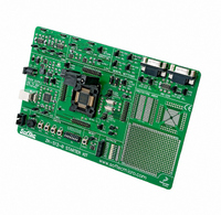
KIT STARTER FOR HCS12
Manufacturer
SofTec Microsystems SRL
Type
Starter Kitr
Specifications of ZK-S12-B
Contents
Board, Cable, Software, Datasheets and User Manual
For Use With/related Products
Freescale HCS12(X) Family (80-LQFP ZIF Socket)
Lead Free Status / RoHS Status
Contains lead / RoHS non-compliant
Other names
520-1037


2.
3.
4.
5.
6.
7.
8.
A “POWER SUPPLY” section which accepts a 12 V DC voltage
(used for the LIN and CAN transceivers) and, thanks to the built-in
switching power supply, provides a regulated VDD voltage for the
rest of the board. A jumper (“VDD SEL”) allows two different
microcontroller VDD voltages (3.3 V or 5.0 V) to be selected. An
additional linear power supply regulator provides the 5.0 V voltage
required by the “USB TO BDM INTERFACE” section.
A built-in “USB TO BDM INTERFACE” section which allows the host
PC to communicate with the microcontroller through a standard USB
interface. USB 2.0 is fully supported. When using an external in-
circuit debugger (via the BDM connector), the “USB TO BDM
INTERFACE” circuitry must be bypassed by removing the “RESET
ENA” and “BKGD ENA” jumpers.
A standard BDM connector for in-circuit debugging/programming;
A “RESET” section containing the reset supervisor circuitry and a
push-button connected to the MCU Reset pin. The reset supervisor
circuitry (enabled by default) can be disabled by removing the “LVD
ENA” jumper.
An “INPUTS” section containing:
An “OUTPUTS” section containing eight high-efficiency (low-current)
LEDs connected to Port B, together with eight jumpers to
connect/disconnect each of the eight LEDs to/from their respective
Port B pins.
A “RS-232” section providing two RS-232 channels connected to the
microcontroller’s SCI0 and SCI1 serial communication interfaces.
Each RS-232 channel can be configured as DTE (Data
Transmission Equipment) or DCE (Data Communication Equipment)
via the relative jumper (“RS-232 x DTE/DCE SEL”). The
microcontroller’s RX and TX lines used by the RS-232 transceivers
are shared with the LIN trasceivers’ RX and TX lines, respectively.
Use the “RXDx SEL” and “TXDx SEL” jumpers in the “SERIAL
A connector area to access the I/O pins of the microcontroller
for expansion prototyping;
Three clock sources: a provision for a clock module, a 16 MHz
crystal in Pierce configuration and a 16 MHz crystal in Colpitts
configuration, selectable via the “OSC SEL” and “XCLK#=0”
jumpers;
A jumper (“XFC SEL”) allowing either the provided RC loop
filter (needed for the microcontroller’s internal PLL) or a user-
made RC loop filter to be enabled;
Two jumpers (“VRH SEL” and “VRL SEL”) which allow the
high and low voltage reference for the MCU internal A/D
converter to be defined;
A “VREGEN” jumper allowing the on-chip voltage regulator to
be enabled or disabled;
Two jumpers (“MODA=1” and “MODB=1”) which allow the
MCU operating mode upon reset to be defined.
Four push-buttons, connected to PP0, PP1, PP2 and PP3;
Eight general-purpose DIP-switches connected to Port T;
A potentiometer, together with a jumper to connect/disconnect
to/from PAD00.
ZK-S12-B User's Manual
Page 2
Related parts for ZK-S12-B
Image
Part Number
Description
Manufacturer
Datasheet
Request
R


Part Number:
Description:
KIT STARTER FOR MC68HC908AB/S/Z
Manufacturer:
SofTec Microsystems SRL
Datasheet:
Part Number:
Description:
KIT STARTER FOR MC68HC908EY
Manufacturer:
SofTec Microsystems SRL
Datasheet:
Part Number:
Description:
KIT STARTER FOR MC68HC908LJ/LK
Manufacturer:
SofTec Microsystems SRL
Datasheet:

Part Number:
Description:
PROG HEAD FOR MP8011A 44-PLCC
Manufacturer:
SofTec Microsystems SRL

Part Number:
Description:
KIT STARTER USB FOR MC9S08GB60
Manufacturer:
SofTec Microsystems SRL
Datasheet:

Part Number:
Description:
KIT STARTER USB FOR ST7FLITE2
Manufacturer:
SofTec Microsystems SRL
Datasheet:
Part Number:
Description:
KIT STARTER USB FOR MC68HC908QY4
Manufacturer:
SofTec Microsystems SRL
Datasheet:

Part Number:
Description:
KIT DESIGN FOR ST7
Manufacturer:
SofTec Microsystems SRL
Datasheet:
Part Number:
Description:
KIT DESIGN USB FOR HCO8
Manufacturer:
SofTec Microsystems SRL
Datasheet:
Part Number:
Description:
KIT DESIGN USB FOR HCO8
Manufacturer:
SofTec Microsystems SRL
Datasheet:

Part Number:
Description:
KIT DESIGN USB FOR HCO8
Manufacturer:
SofTec Microsystems SRL
Datasheet:
Part Number:
Description:
KIT DESIGN USB FOR HCO8
Manufacturer:
SofTec Microsystems SRL
Datasheet:
Part Number:
Description:
KIT DESIGN USB FOR HCS12
Manufacturer:
SofTec Microsystems SRL
Datasheet:
Part Number:
Description:
KIT DESIGN USB FOR HCS12
Manufacturer:
SofTec Microsystems SRL
Datasheet: