ZK-S12-B SofTec Microsystems SRL, ZK-S12-B Datasheet - Page 3
ZK-S12-B
Manufacturer Part Number
ZK-S12-B
Description
KIT STARTER FOR HCS12
Manufacturer
SofTec Microsystems SRL
Type
Starter Kitr
Specifications of ZK-S12-B
Contents
Board, Cable, Software, Datasheets and User Manual
For Use With/related Products
Freescale HCS12(X) Family (80-LQFP ZIF Socket)
Lead Free Status / RoHS Status
Contains lead / RoHS non-compliant
Other names
520-1037


9.
10. The “SERIAL SETTINGS” section has four jumpers that allow the
11. The “CAN” section contains two fault-tolerant (up to 125 Kbaud)
12. A prototype area features both a standard, thru-hole area (for
4
SETTINGS” section of the board to select whether to use the RS-
232, LIN, or to free the microcontroller’s RX and TX lines. Two 9-pin,
D-Sub female connectors are provided for each RS-232 channel.
The “LIN” section contains two LIN transceivers, each capable of a
speed of up to 100 Kbps in fast mode. Every LIN node can be
configured as a master node via its respective “MASTER NODEx
ENA” jumper, which inserts a 900 Ohm resistor between the LIN
bus line and the LIN transceiver power supply line. The LIN
transceivers can be powered either by the Starter Kit’s internal 12 V
DC reference, or by the LIN network itself, via the “TRANSCEIVER
SUPPLY SEL” jumper. Analogously, the LIN network can be
supplied by the Starter Kit’s internal 12 V DC reference via the “LIN
SUPPLY ENA” jumper. The microcontroller’s RX and TX lines used
by the LIN transceivers are shared with the RS-232 transceivers’ RX
and TX lines, respectively. Use the “RXDx SEL” and “TXDx SEL”
jumpers in the “SERIAL SETTINGS” section of the board to select
whether to use the RS-232, LIN, or to free the microcontroller’s RX
and TX lines associated with these nodes. Two 3x1 male header
connectors are provided to interface to an external LIN bus.
uses of the SCI0 and SCI1 peripherals of the microcontroller to be
chosen. The SCI0 peripheral can be connected to the LIN0 node or
to the RS-232 channel 0, or can be freed by removing all jumpers.
The SCI1 peripheral can be connected to the LIN1 node or to the
RS-232 channel 1, or can be freed by removing all jumpers.
CAN transceivers. The TX and RX signals of CAN nodes CAN0 and
CAN4 can be disconnected (by removing the respective “CANx TX
ENA” and “CANx RX ENA” jumpers) from the microcontroller’s
respective pins. Two 3x1 male header connectors are provided to
interface to an external CAN bus.
mounting traditional components) and a SMD area (for soldering
SMD components). Additionally, all of the board’s supply lines (12 V,
5 V, VDD and GND lines) are provided.
11
2
3
6
1
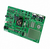
The ZK-S12-B Starter Kit
9
5
10
7
ZK-S12-B User's Manual
12
8
Page 3
Related parts for ZK-S12-B
Image
Part Number
Description
Manufacturer
Datasheet
Request
R


Part Number:
Description:
KIT STARTER FOR MC68HC908AB/S/Z
Manufacturer:
SofTec Microsystems SRL
Datasheet:
Part Number:
Description:
KIT STARTER FOR MC68HC908EY
Manufacturer:
SofTec Microsystems SRL
Datasheet:
Part Number:
Description:
KIT STARTER FOR MC68HC908LJ/LK
Manufacturer:
SofTec Microsystems SRL
Datasheet:

Part Number:
Description:
PROG HEAD FOR MP8011A 44-PLCC
Manufacturer:
SofTec Microsystems SRL

Part Number:
Description:
KIT STARTER USB FOR MC9S08GB60
Manufacturer:
SofTec Microsystems SRL
Datasheet:

Part Number:
Description:
KIT STARTER USB FOR ST7FLITE2
Manufacturer:
SofTec Microsystems SRL
Datasheet:
Part Number:
Description:
KIT STARTER USB FOR MC68HC908QY4
Manufacturer:
SofTec Microsystems SRL
Datasheet:

Part Number:
Description:
KIT DESIGN FOR ST7
Manufacturer:
SofTec Microsystems SRL
Datasheet:
Part Number:
Description:
KIT DESIGN USB FOR HCO8
Manufacturer:
SofTec Microsystems SRL
Datasheet:
Part Number:
Description:
KIT DESIGN USB FOR HCO8
Manufacturer:
SofTec Microsystems SRL
Datasheet:

Part Number:
Description:
KIT DESIGN USB FOR HCO8
Manufacturer:
SofTec Microsystems SRL
Datasheet:
Part Number:
Description:
KIT DESIGN USB FOR HCO8
Manufacturer:
SofTec Microsystems SRL
Datasheet:
Part Number:
Description:
KIT DESIGN USB FOR HCS12
Manufacturer:
SofTec Microsystems SRL
Datasheet:
Part Number:
Description:
KIT DESIGN USB FOR HCS12
Manufacturer:
SofTec Microsystems SRL
Datasheet: