STEVAL-TCS003V1 STMicroelectronics, STEVAL-TCS003V1 Datasheet - Page 43
STEVAL-TCS003V1
Manufacturer Part Number
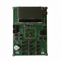
STEVAL-TCS003V1
Description
BOARD DEMO EXPANDER STMPE2403
Manufacturer
STMicroelectronics
Specifications of STEVAL-TCS003V1
Main Purpose
Interface, GPIO Expander
Embedded
No
Utilized Ic / Part
STMPE2403
Primary Attributes
8/16/24-Bit 24-Port GPIO Expander over I2C
Secondary Attributes
3 8-Bit PWM Output for LEDs, Keyboard Matrix Scan, Special Key Support
Lead Free Status / RoHS Status
Lead free / RoHS Compliant
Other names
497-8206
Available stocks
Company
Part Number
Manufacturer
Quantity
Price


STMPE2403
11.3
11.4
PWM Instruction Channel x (PWMICx)
This PWMICx is the dataport that allows the instructions to be loaded into the PWM
channel. The loading of the instructions is achieved by continuously writing to this dataport.
As this dataport address falls on the non-auto increment region, continuous write operation
on I
independent PWM channels. To access these dataports, the corresponding ENx in the
PWMCS register must be set to 0 first to put the PWM channel in reset state.
Table 41. Bit description
PWM commands
The STMPE2403 PWM Controller works as a simple MCU, with program space of 64
instructions and a simple instruction set. The instructions are all 16 bits in length. The 3
most significant bits are used to identify the commands.
Table 42. PWM commands
Reset Value
Read/Write
Bits
7:0
Instruction
2
C will write into the same dataport address. The ‘x’ value is from 0 to 2 as there are 3
Bit
RAMP
Name
IB[y]
RW
IB7
This instruction starts the PWM counters and set the pwm_x_out with the result
from the counting.
Prescale: (0 or 1)
‘0’ - divide 32KHz clock by 16
‘1’ – divide 32KHz clock by 512
Step Time: (1-63)
One ramp increment done in (step time) x (clock after prescale)
Sign: (0 or 1)
“0” – increase PWM output
‘1’ – decrease PWM output
Increment: (0-127)
The number of increment/decrement cycles
7
0
PWM Instruction Channel x, where y is 7 to 0
As an instruction is 16-bit width, writing the instruction into this 8-bit PWMICx
dataport requires two 8-bit data write. The most significant byte of the 16-bit
instruction is to be written in first and followed by the least significant byte of the
instruction. The same effect applies to the read operation.
RW
IB6
6
0
RW
IB5
5
0
RW
IB4
4
0
Description
Description
RW
IB3
3
0
RW
IB2
2
0
PWM controller
RW
IB1
1
0
RW
IB0
0
0
43/63
Related parts for STEVAL-TCS003V1
Image
Part Number
Description
Manufacturer
Datasheet
Request
R

Part Number:
Description:
BOARD EVAL FOR ST802RT1
Manufacturer:
STMicroelectronics
Datasheet:

Part Number:
Description:
EVAL BOARD 100 BASE T
Manufacturer:
STMicroelectronics
Datasheet:

Part Number:
Description:
BOARD ELECT FISCAL CASH REGISTER
Manufacturer:
STMicroelectronics
Datasheet:
Part Number:
Description:
BOARD EVAL FOR ST802RT1A
Manufacturer:
STMicroelectronics
Datasheet:

Part Number:
Description:
2 kW/100 V RF demonstration board for 3 T MRI based on the STAC4932B
Manufacturer:
STMICROELECTRONICS [STMicroelectronics]
Datasheet:

Part Number:
Description:
BOARD EVAL FOR MEMS SENSORS
Manufacturer:
STMicroelectronics
Datasheet:
Part Number:
Description:
EVALBOARD/STEVAL-ISV014V1
Manufacturer:
STMicroelectronics

Part Number:
Description:
BOARD EVAL FOR VACUUM CLEANER
Manufacturer:
STMicroelectronics
Datasheet:

Part Number:
Description:
KIT DEV STARTER ST10F276Z5
Manufacturer:
STMicroelectronics
Datasheet:

Part Number:
Description:
BOARD LED CTLR/DVR STLED316S
Manufacturer:
STMicroelectronics
Datasheet:
Part Number:
Description:
STMicroelectronics [RIPPLE-CARRY BINARY COUNTER/DIVIDERS]
Manufacturer:
STMicroelectronics
Datasheet:
Part Number:
Description:
STMicroelectronics [LIQUID-CRYSTAL DISPLAY DRIVERS]
Manufacturer:
STMicroelectronics
Datasheet:
Part Number:
Description:
BOARD EVAL FOR MEMS SENSORS
Manufacturer:
STMicroelectronics
Datasheet: