MT9V022I77ATMH ES Aptina LLC, MT9V022I77ATMH ES Datasheet - Page 8
MT9V022I77ATMH ES
Manufacturer Part Number
MT9V022I77ATMH ES
Description
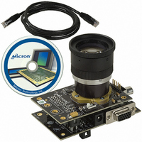
KIT HEAD BOARD FOR MT9V022
Manufacturer
Aptina LLC
Datasheet
1.MT9V022I77ATCH_ES.pdf
(15 pages)
Specifications of MT9V022I77ATMH ES
Lead Free Status / RoHS Status
Lead free / RoHS Compliant
Other names
557-1204


Pixel Binning
Power Reduction Modes
Standby Control
Monitor Mode Control
Thermometer
Electrical Specifications
Table 2:
PDF:09005aef8201ffc3/Source: 09005aef81ff2525
MT9V022_Product_Brief - Rev. A 1/06 EN
V
V
I
V
V
I
I
V
I
V
I
VAAPIX
I
IN
OH
OL
PWR
PWR
PIX
OH
OL
AA
IH
IL
DD
Symbol
A
D
Input high voltage
Input low voltage
Input leakage current
Output high voltage
Output low voltage
Output high current
Output low current
Analog power supply
Analog supply current
Digital power supply
Digital supply current
Pixel array power supply
Pixel supply current
DC Electrical Characteristics
V
PWR
= 3.3V ±0.3V; T
Definition
In addition to windowing mode— in which smaller resolution (CIF, QCIF, user-selected
size frame) is obtained by selecting a small window from the sensor array—the MT9V022
provides the ability to show the entire image captured by the pixel array with smaller res-
olution by pixel binning. Pixel binning is performed by combining signals from adjacent
pixels by averaging. There are two options: binning 2 and binning 4.
When binning 2 is on, 4 pixel signals from 2 adjacent rows and columns are combined.
In the case of binning 4 mode, 16 pixels are combined from 4 adjacent rows and col-
umns. Binning may be used in conjunction with image flip. The binning operation
increases SNR but decreases resolution. Enabling row bin2 and row bin4 improves frame
rate by 2x and 4x, respectively. Column binning does not increase the frame rate.
The user may set the sensor in standby mode by setting STANDBY HIGH. Once the
MT9V022 detects that STANDBY is asserted, it completes the current frame before dis-
abling the digital logic, internal clocks, and analog power enable signal. To release the
sensor out from the standby mode, reset STANDBY back to LOW.
In this mode, the MT9V022 first captures a programmable number of frames and then
goes into a sleep period for five minutes. During the sleep period, all of the analog cir-
cuitry of the MT9V022 is powered-down and only a small portion of the digital circuitry
remains powered.
The MT9V022 thermometer circuit provides a digital output vs. temperature that is
accessible via the serial interface. The resolution of the thermometer is approximately 1
LSB per degree Celsius.
A
= Ambient = 25
No pull-up resistor;
V
I
I
V
V
Default settings
Default settings
Default settings
Default settings, C
Default settings
Default settings
OH
OL
IN
OH
OL
= 4.0mA
= V
= -4.0mA
= 0.7
= V
°
MT9V022: 1/3-Inch Wide-VGA Digital Image Sensor
C
PWR
DD
Condition
- 0.7
or V
8
GND
LOAD
= 10pF
Micron Technology, Inc., reserves the right to change products or specifications without notice.
V
V
PWR
PWR
-15.0
Min
-0.3
-9.0
3.0
3.0
3.0
0.5
—
–
–
–
-0.5
-0.7
Electrical Specifications
35.0
35.0
Typ
3.3
3.3
3.3
1.4
©2006 Micron Technology, Inc. All rights reserved.
–
–
–
–
–
–
–
V
PWR
Max
15.0
60.0
0.8
0.3
9.0
3.6
3.6
3.6
3.0
60
–
–
+0.3
Unit
mA
mA
mA
mA
mΑ
μA
V
V
V
V
V
V
V
Related parts for MT9V022I77ATMH ES
Image
Part Number
Description
Manufacturer
Datasheet
Request
R

Part Number:
Description:
1/3-Inch Wide-VGA CMOS Digital Image Sensor
Manufacturer:
Aptina Imaging Corporation

Part Number:
Description:
SENSOR IMAGE VGA COLOR CMOS PLCC
Manufacturer:
Aptina LLC
Datasheet:

Part Number:
Description:
IC SENSOR IMAGE COLOR 48CLCC
Manufacturer:
Aptina LLC
Datasheet:

Part Number:
Description:
SENSOR IMAGE 1.3MP CMOS 48-CLCC
Manufacturer:
Aptina LLC
Datasheet:

Part Number:
Description:
SENSOR IMAGE 2MP CMOS 48-CLCC
Manufacturer:
Aptina LLC
Datasheet:

Part Number:
Description:
SENSOR IMAGE VGA MONO 52IBGA
Manufacturer:
Aptina LLC
Datasheet:

Part Number:
Description:
SENSOR IMAGE VGA COLOR 48CLCC
Manufacturer:
Aptina LLC
Datasheet:

Part Number:
Description:
SENSOR IMAGE COLOR CMOS 48-PLCC
Manufacturer:
Aptina LLC
Datasheet:

Part Number:
Description:
KIT HEAD BOARD FOR MT9P031
Manufacturer:
Aptina LLC
Datasheet:

Part Number:
Description:
KIT HEAD BOARD FOR MT9D131
Manufacturer:
Aptina LLC
Datasheet:
Part Number:
Description:
SENSOR IMAGE VGA COLOR CMOS PLCC
Manufacturer:
Aptina LLC
Datasheet:
Part Number:
Description:
IC SENSOR IMAGE COLOR 48CLCC
Manufacturer:
Aptina LLC
Datasheet:
Part Number:
Description:
SENSOR IMAGE 2MP CMOS 48-CLCC
Manufacturer:
Aptina LLC
Datasheet:
