H5CX-A11-N AC100-240 Omron, H5CX-A11-N AC100-240 Datasheet - Page 8
H5CX-A11-N AC100-240
Manufacturer Part Number
H5CX-A11-N AC100-240
Description
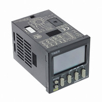
RELAY TIMER DGTL SPDT 100/240VAC
Manufacturer
Omron
Series
H5CXr
Specifications of H5CX-A11-N AC100-240
Mounting Type
Socket
Relay Type
Integrated
Function
Programmable (Multi-Function)
Circuit
SPDT (1 Form C)
Delay Time
0.001 Sec ~ 9999 Hrs
Output Type
Mechanical Relay
Contact Rating @ Voltage
5A @ 250VAC
Voltage - Supply
100 ~ 240VAC
Termination Style
11 Pin Socketable
Timing Adjustment Method
DIP Switches
Timing Initiate Method
Input Voltage, Trigger Signal
Timing Range
0.001 s to 9999 Hrs
Supply Voltage
100 V to 240 V
Current Rating (max)
100 mA
Display Type
4 Digit LCD Backlight
Product
Digital Timer
Time Range
0.001s-9999hrs
Power Consumption
6.2VA
Reset Time
20ms
Signal Input Type
PNP/NPN
Supply Voltage Max
240VAC
Character Size
11.5mm
Switch Function
SPDT
Supply Voltage Min
100VAC
Rohs Compliant
Yes
No. Of Digits / Alpha
4
Lead Free Status / RoHS Status
Lead free / RoHS Compliant
Lead Free Status / RoHS Status
Lead free / RoHS Compliant, Lead free / RoHS Compliant
Other names
H5CXA11NAC100240
Z2998
Z2998


8
H5CX-A@-N/-L@-N
Connections
Block Diagram
Note: Basic insulation is provided between the power supply circuit and the input circuits. However, basic insulation is not provided in the
Terminal Arrangement
Confirm that the power supply meets specifications before use.
Note: Do not connect unused terminals as relay terminals.
Instantaneous
contact output
OUT1
Signal
Signal
(-)
Reset
Reset
Gate
H5CX-@D-N.
0V
6
1
Unused
0V
Internal circuit
7
2
(+)
Unused
Contact output
3
0V
4
3
2
8
3
Input circuits
2
(-)
5
(-)
4
1
1
Output circuit
6 7
9
4
(Basic insulation)
11
3
2
5
8
(+)
(+)
(–)
10
4
1
5
8
6
7
9
H5CX-A11-N/-A11D-N
H5CX-L8E-N/-L8ED-N
5
8
(+)
H5CX-L8-N/-L8D-N
H5CX-A-N/-AD-N
Internal circuit
Internal circuit
6
7
(Basic insulation)
Internal control
Terminals 1 and 6 of the H5CX-AD-N
are connected internally.
circuit
Internal circuit
Contact
output
Contact
output
Terminals 1 and 2 of the H5CX-L8D-N
are connected internally.
contact output
Time-limit
OUT2
Power supply
(See note.)
Terminals 2 and 3 of the
H5CX-A11D-N are
connected internally.
Key switch circuit
circuit
Display circuit
Transistor Output
• The transistor output of
• The diode connected to
Signal
Signal
Reset
(-)
Reset
Gate
the H5CX is insulated
from the internal circuitry
by a photocoupler, so the
transistor output can be
used as both NPN and
PNP output.
the collector of the output
transistor is used to
absorb inverted voltage
that is generated when an
inductive load is
connected to the H5CX.
0V
6
1
Unused
0V
7
2
(+)
Transistor output
Unused
3
0V
4
3
2
8
3
2
(-)
5
(-)
4
1
1
6 7
9
4
11
(+)
5
8
(+)
10
Unused
5
8
6
7
9
H5CX-A11S-N/-A11SD-N
H5CX-L8S-N/-L8SD-N
H5CX-AS-N/-ASD-N
Internal circuit
Internal circuit
Terminals 1 and 6 of the H5CX-ASD-N
are connected internally.
NPN Output
Transistor
output
Transistor
output
Terminals 1 and 2 of the H5CX-L8SD-N
are connected internally.
Power for load
Timer
+
Terminals 2 and 3 of the
H5CX-A11SD-N are
connected internally.
Power for load
Load
+
PNP Output
Load
Inductive
load
Power for load
+
Related parts for H5CX-A11-N AC100-240
Image
Part Number
Description
Manufacturer
Datasheet
Request
R

Part Number:
Description:
Relay; E-Mech; Timing; Multi-Function; Cur-Rtg 5A; Ctrl-V 100-240AC; Socket Mnt; 11 Pin
Manufacturer:
Omron Automation
Datasheet:

Part Number:
Description:
RELAY TIMER DGTL SPDT 100/240VAC
Manufacturer:
Omron
Datasheet:
Part Number:
Description:
G6S-2GLow Signal Relay
Manufacturer:
Omron Corporation
Datasheet:
Part Number:
Description:
Compact, Low-cost, SSR Switching 5 to 20 A
Manufacturer:
Omron Corporation
Datasheet:
Part Number:
Description:
Manufacturer:
Omron Corporation
Datasheet:
Part Number:
Description:
Manufacturer:
Omron Corporation
Datasheet:
Part Number:
Description:
Manufacturer:
Omron Corporation
Datasheet:
Part Number:
Description:
Manufacturer:
Omron Corporation
Datasheet:
Part Number:
Description:
Manufacturer:
Omron Corporation
Datasheet:
Part Number:
Description:
Manufacturer:
Omron Corporation
Datasheet: