58442-1 Tyco Electronics, 58442-1 Datasheet - Page 3
58442-1
Manufacturer Part Number
58442-1
Description
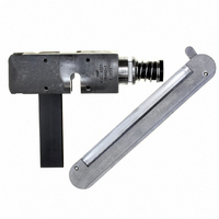
TOOL HEAD ASSEMBLY RCPT MTA 100
Manufacturer
Tyco Electronics
Series
MTA-100r
Type
Hand Toolr
Specifications of 58442-1
Crimp Application
Connectors
Product
Crimping, Stripping & Cutting Tools & Drills
Description/function
Crimp tool assembly for discrete wire MTA-100 receptacles
For Use With
MTA-100 Feed-Through Receptacles
Lead Free Status / RoHS Status
Not applicable / Not applicable
Lead Free Status / RoHS Status
na, Not applicable / Not applicable
Other names
58442-1
A9973
A9973


B. Wire Not Deep Enough
If the wire is not inserted deeply enough in contact
slot, remove the head from the tool and turn the
adjuster counterclockwise one–sixth of a revolution.
The wire insertion depth will be increased by
approximately 0.203 [.008]. Repeat the test procedure
as described in Paragraph 3.1.
4. TERMINATING PROCEDURE
Determine the wire size and select the appropriate
connector. Connectors are color–coded according to
the wire sizes they will accommodate.
Rev A
Note:
1
/
6
Counterclockwise to Increase
Wire Insertion Depth
turn equals 0.20 [.008] adjustment.
Pneumatic Pistol
Grip Handle
Assembly
Left Side
of Head
Figure 3
Index Rib
(Figure 4)
Clockwise to Reduce
Wire Insertion Depth
Wire(s)
MTA Terminating Head 58442–1
Adjuster
Figure 4
1. Insert connector into left side of head as shown
in Figure 4.
2. Align the contact to be terminated with the wire
inserter.
3. Be sure the locating pawl rests between the
connector index ribs.
4. Insert an unstripped wire into the funnel area
between the contact and the wire inserter until it
bottoms on the tool base.
5. Depress trigger (or squeeze cam handle) of
pistol grip handle assembly and hold it until the
inserter bottoms or the ratchet releases.
6. Release trigger (or cam handle). The inserter
will retract and the feed slide will automatically
advance connector to next contact position.
NOTE
7. Repeat Steps 2 through 6 until all contacts have
been terminated.
8. Inspect each termination according to the
procedure in Section 5, INSPECTION, and
according to Application Specification 114–1031.
The locating pawl will move up and down as the
connector is automatically advanced through the
head. However, if movement is obstructed, or if
desirable, the locating pawl can be depressed
and the connector moved manually out the
RIGHT side of the head.
Locating Pawl
Feed Slide
Wire Sub–Assembly
Retainer
408–9603
3 of 4