58442-1 Tyco Electronics, 58442-1 Datasheet - Page 4
58442-1
Manufacturer Part Number
58442-1
Description
TOOL HEAD ASSEMBLY RCPT MTA 100
Manufacturer
Tyco Electronics
Series
MTA-100r
Type
Hand Toolr
Specifications of 58442-1
Crimp Application
Connectors
Product
Crimping, Stripping & Cutting Tools & Drills
Description/function
Crimp tool assembly for discrete wire MTA-100 receptacles
For Use With
MTA-100 Feed-Through Receptacles
Lead Free Status / RoHS Status
Not applicable / Not applicable
Lead Free Status / RoHS Status
na, Not applicable / Not applicable
Other names
58442-1
A9973
A9973


5. TERMINATION INSPECTION
Inspect each termination to ensure the following:
Refer to Application Specification 114–1031 for more
inspection information.
6. TOOLING INSPECTION/MAINTENANCE
The following procedures have been established to
ensure the quality and reliability of your tooling. The
tooling should be checked daily, and a more detailed
inspection should be performed by your quality control
group on a regular basis.
6.1. Daily Maintenance
Each operator should be aware of, and responsible
for, the following steps of maintenance:
6.2. Quality Control Maintenance
Regular inspections should be performed by your
quality control personnel. A record of quality control
4 of 4
1. Conductor is terminated past the lead–in
transition and is about halfway in the contact slot.
2. Insulation is 1.78 to 2.16 [.070 to .085] beyond
the front contact beam.
3. Wire is NOT bottomed in contact slot.
4. Contact beams are NOT deformed. If damage is
apparent, replace contacts in accordance with the
instructions packaged with the connector.
5. Insulation of wire is NOT nicked or cut in any
area other than the two wire slots.
6. Wire extends below the strain–relief features of
the connector.
1. Remove dust, moisture, and other contaminants
with a clean brush, or soft, lint–free cloth. Do NOT
use objects that could damage the tool.
2. Make sure all components are in place and
properly secured.
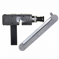
3. Actuate the handle assembly to ensure
mechanisms inside the head move smoothly.
(Figure 2)
MTA Terminating Head 58442–1
inspections should remain with the personnel respon-
sible for the tool. We recommend one inspection a
month; however, operator skill, amount of use, ambi-
ent working conditions, and your company’s
established standards are all factors in establishing
frequency of inspections.
7. REPAIR AND REPLACEMENT
Customer–replaceable parts are listed on customer
drawing 58442. A complete inventory should be
stocked and controlled to prevent lost time when
replacement of parts is necessary. Parts other than
those listed should be replaced by Tyco Electronics to
ensure quality and reliability. Order replacement parts
through your Tyco Electronics Representative, or call
1–800–526–5142, or send a facsimile of your
purchase order to 717–986–7605, or write to:
For customer repair service, please contact a Tyco
Electronics Representative at 1–800–526–5136.
8. REVISION SUMMARY
Revisions to this instruction sheet per EC
0990–0826–03 include:
1. Remove any accumulated film with a suitable
cleaning agent that will NOT affect plastic material.
2. Make sure all components are in place and are
properly secured.
3. Make a few test terminations and inspect the
termination in accordance with Section 5,
INSPECTION.
4. Check for chipped, cracked, worn, or broken
areas. If damage is evident, repair is necessary.
See Section 7, REPAIR.
CUSTOMER SERVICE (038–035)
TYCO ELECTRONICS CORPORATION
PO BOX 3608
HARRISBURG PA 17105–3608
S Updated document to corporate requirements
S Deleted Paragraph 3.4 from document
S Deleted reference to “Feed Adjustment Screw”
in Figure 4
408–9603
Rev A