318451-2 Tyco Electronics, 318451-2 Datasheet - Page 2
318451-2
Manufacturer Part Number
318451-2
Description
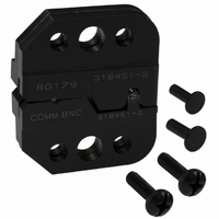
DIE SET
Manufacturer
Tyco Electronics
Series
Pro-Crimper™ IIIr
Type
Crimp Toolr
Specifications of 318451-2
Connector Type
Coax Connectors
Crimp Handle
Tyco/AMP 318451-1
Crimp Or Cable Size
RG/U-79, 161, 187
Features
"O" / Commercial
Crimp Application
Coaxial
Product
Crimping, Stripping & Cutting Tools & Drills
For Use With
75 Ohm BNC RF/Coaxial Connectors
Lead Free Status / RoHS Status
Not applicable / Not applicable
Lead Free Status / RoHS Status
na, Not applicable / Not applicable
Other names
318451-2
A24630
A24630


Wire
Anvil
2 of 5
2. Place the wire anvil and insulation anvil so that
their chamfered sides and their marked surfaces
face outward, when mounted in the moving jaw of
the tool frame.
3. Insert the two die retaining pins.
4. Insert the short die retaining screw through the
jaw and through both anvil dies, and tighten the
screw just enough to hold the dies in place. Do not
tighten the screw completely at this time.
5. Place the wire indenter and insulation indenter
so that their chamfered sides and their marked
surfaces face outward, when mounted in the
stationary jaw of the tool frame.
6. Insert the two die retaining pins.
7. Insert the long die retaining screw through the
jaw and through both indenter dies, and tighten the
screw just enough to hold the dies in place. Do not
tighten the screw completely at this time.
8. Carefully close the tool handles, making sure
that the anvils and indenters align properly.
Continue closing the tool handles until the ratchet
in the tool frame has engaged sufficiently to hold
the anvils and indenters in place, then tighten both
die retaining screws.
9. To remove, close the tool handles until the
ratchet releases, remove the two die retaining
screws and the four die retaining pins, and slide
the anvils and indenters out of the tool jaws.
Wire
Indenter
Insulation
Anvil
Insulation
Indenter
Center Contact
Crimping Chamber
Ferrule Crimping
Chamber
PRO–CRIMPER III Hand Tool Assembly 318451–1
Figure 2
4. CRIMPING PROCEDURE
Slide the ferrule onto the cable and strip the cable
according to the dimensions provided in the
instructions packaged with the connector. Take care
not to nick or cut wire strands. Proceed as follows:
4.1. Center Contact
4.2. Ferrule
NOTE
1. Slide center contact onto stripped conductor.
Insert center contact assembly into the partially
closed center contact crimping chamber on the
anvil die. Make sure the center contact flange is
against the edge of the die as shown in Figure 3.
2. While holding the cable in place, crimp the
center contact by closing the tool handles until the
ratchet releases.
3. Allow the handles to open fully, and remove the
crimped center contact from the die assembly.
1. Flare the cable braid and insert the crimped
center contact into the connector body until the
cable dielectric is against the dielectric inside the
connector body. The flared braid will then fit over
the support sleeve of the connector body.
(Figure 4)
This tool is provided with a crimp adjustment
feature. Initially, the crimp height should be
verified as specified in Figures 5 and 6. Refer to
Section 5, INSPECTION, and Section 6, CRIMP
HEIGHT ADJUSTMENT, to verify crimp before
using the tool to crimp desired connectors and
wire sizes.
(Figure 3)
Die Retaining
Pins
Die Retaining
Screws
408–4217
Rev A