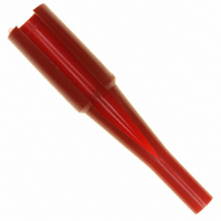
1643914-1 Tyco Electronics, 1643914-1 Datasheet - Page 4

1643914-1
Manufacturer Part Number
1643914-1
Description
TOOL INSERTION/REMOVAL SIZE #8
Manufacturer
Tyco Electronics
Series
ELCONr
Type
Extraction Toolr
Specifications of 1643914-1
Tool Type
Insertion/Extraction Tool
Description/function
Red tool
Wire Gauge Range
8
Product
Insertion / Extraction Tool
For Use With/related Products
Circular Connector Contacts
For Use With
A36295 - CONN SOCKET #8 PCBA36294 - CONN SOCKET #8 CRIMP REMOVABLEA36280 - CONN PIN #8 PCB SILVERA36279 - CONN PIN #8 CRIMP SILVER
Lead Free Status / RoHS Status
Not applicable / Not applicable
Other names
A36311
3.4. Special Features
The length of the pin contacts (except size 0 and 4), designated by standard, pre--mate, and post--mate, varies
among contact sizes and applies to the portion of the contact that protrudes from the connector after insertion
(socket length does not include depth of the connector standoff). Mating socket contacts accept all pin lengths
of the same contact size. The length of pin and socket contacts, as described, are shown in Figure 2.
DIncludes hot plug contacts
Probe--proof socket contacts size 0 are designed with a protective cap to provide additional probe--proof
protection along with the crown band. This cap must not be removed from the contact. See Figure 3.
Some crimp type contacts feature a sight hole located on the side of the wire barrel or in the center of the
inside of the wire barrel. See Figure 3. Crimp contacts are rear--insertable and removeable. PC board tail are
rear--insertable and non--removable.
The connector contact cavities contain retention clips. The retention clip is an important feature in holding the
crimped contact in the connector. When the contact is fully inserted, the retention clips engage the shoulder of
the contact and prevent backing out during mating of the connector.
3.5. Wire Selection and Preparation
The contacts will accept stranded wire sizes 24 through 1/0 AWG. Proper strip length is necessary to properly
insert the wire into the contact. The strip length of the wire is shown in Figure 4.
Crown Band
4 of 17
CAUTION
Typical Socket Contact Size 0
CONTACT SIZE
CONTACT SIZE
!
12D
20
16
8
4
0
0
Reasonable care must be taken not to nick, scrape, or cut any strands during the stripping operation.
Connector
“A”
10.92 [.430] Probe Proof
(STANDARD)
10.92 [.430]
10.92 [.430]
12.95 [.510]
12.57 [.495]
8.12 [.320]
8.38 [.330]
Pin Contact
PROBE PROOF CRIMP TYPE AND SOLDER TYPE
Typical Probe- - Proof Socket Contact Size 0
Protective
Cap
Tyco Electronics Corporation
CONTACT LENGTH (DIMENSION “A”)
PRE- - MATE
Probe Proof
11.93 [.470]
12.19 [.480]
11.68 [.460]
12.19 [.480]
Figure 3
Figure 2
PIN
------
------
Socket Contact
POST- - MATE
6.85 [.270]
7.36 [.290]
9.90 [.390]
------
------
------
Crimp Type Pin Contact
Sight Hole
With Sight Hole
“A”
Connector
SOLDER TYPE
SOLDER TYPE
CONTACT
CONTACT
4.06 [.160]
4.06 [.160]
5.33 [.210]
6.85 [.270]
------
------
Rev D


