1643914-1 Tyco Electronics, 1643914-1 Datasheet - Page 6
1643914-1
Manufacturer Part Number
1643914-1
Description
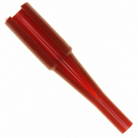
TOOL INSERTION/REMOVAL SIZE #8
Manufacturer
Tyco Electronics
Series
ELCONr
Type
Extraction Toolr
Specifications of 1643914-1
Tool Type
Insertion/Extraction Tool
Description/function
Red tool
Wire Gauge Range
8
Product
Insertion / Extraction Tool
For Use With/related Products
Circular Connector Contacts
For Use With
A36295 - CONN SOCKET #8 PCBA36294 - CONN SOCKET #8 CRIMP REMOVABLEA36280 - CONN PIN #8 PCB SILVERA36279 - CONN PIN #8 CRIMP SILVER
Lead Free Status / RoHS Status
Not applicable / Not applicable
Other names
A36311


3.7. Threaded Contacts and Guide Posts and Threaded Contacts
3.8. Connector Spacing
Care must be taken to avoid interference between adjacent connectors and/or other components. There is no
required spacing between connectors, however spacing may be dependent on variable hardware used and the
clearance required for mating connectors.
3.9. Panel Cutout
The pin side connector and socket side connector can be installed or removed from either the back or the front
of the panel (front of the panel is recommended). Usually, the socket side connector is mounted in the cabinet
(energized) panel, while the pin side connector is mounted in the drawer (passive) panel. Dimensions for
mounting holes, guide pins (if applicable), and panel cutouts, and maximum panel thickness for rear mounting
are shown in Figure 7.
3.10. Contact Insertion and Extraction
Normally an insertion tool is not required to insert contacts into connectors, but if the wire bundle is large or
individual wires are fragile, using an insertion tool is recommended. Push contact straight into the contact
cavity until it bottoms (an audible click). After inserting contact into connector, pull back lightly on the wire to
ensure contact is fully seated.
The contacts are rear--insertable and rear--releasable; an extraction tool is needed to disengage the connector
retention clips and remove the contact from the back of the connector. Only crimp type and threaded contacts
are removable. Refer to Section 5 for tooling information.
3.11. PC Board Connectors
6 of 17
Chucking Area
Chucking Area
S
S
S
S
NOTE
C. Conductor Location
After crimping, the conductor ends must be flush to the end of the wire barrel. In contacts having a sight
hole, this can be verified by checking that the conductor ends are visible in the sight hole. See Figure 5.
D. Effective Crimp Length
The effective crimp length is the area where the crimp pressure is applied over the length of the wire
barrel.
E. Straightness
After crimping the wire to the contact, the contact must be chucked, and rotated a minimum of 360_. The
point of TIR (total indicator reading) measurement must not exceed the dimensions shown in Figure 6.
A. PC Board Material and Thickness
The pc board material shall be glass epoxy (FR--4 or G--10). The pc board thickness range shall be
1.38 through 5.08 mm [.054 through .200 in.].
i
Threaded guide posts should not exceed a torque limit of 1.7 N
Threaded contacts with M6 threading should not exceed a torque limit of 4.5 N
Threaded contacts with 1/4--20 threading should not exceed a torque limit of 6.8 N
Threaded contacts with M5 threading should not exceed a torque limit of 2.9 N
Each crimp dimension represents the functional range of wire and contact combination. The developed crimp
configuration is unique for each tool design and is acceptable provided the crimp height is within the functional range.
For crimp dimensions relating to a specific tool, refer to the instruction sheet packaged with manual tools and the
applicator log packaged with power tools.
Dial Indicator Probe Placed
H
Here for Measurement of TIR
f M
Tyco Electronics Corporation
Figure 6
Wire
Wire
t f TIR
D
m [15 in.--lb]
WIRE SIZE RANGE
(AWG)
18--12
10--4
1/0
20
D
D
m [40 in.--lb]
m [26 in--lb]
D
m [60 in.--lb]
TIR MEASUREMENT
0.279 [.011]
0.305 [.012]
0 762 [ 030]
0.762 [.030]
(Max)
Rev D