ST203C107MAJ05 AVX Corporation, ST203C107MAJ05 Datasheet - Page 38
ST203C107MAJ05
Manufacturer Part Number
ST203C107MAJ05
Description
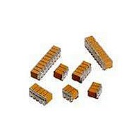
CAP CER 100UF 25V STACKED SMD
Manufacturer
AVX Corporation
Series
TurboCap™r
Specifications of ST203C107MAJ05
Capacitance
100µF
Tolerance
±20%
Temperature Coefficient
X7R
Voltage - Rated
25V
Mounting Type
Surface Mount, MLCC
Operating Temperature
-55°C ~ 125°C
Features
Stacked
Applications
Filtering Switch Mode Power Supplies
Package / Case
10-Stacked SMD, J-Lead
Size / Dimension
0.525" L x 0.300" W (13.34mm x 7.62mm)
Thickness
5.59mm Max
Lead Style
J-Lead
Voltage Rating
25 Volts
Operating Temperature Range
- 55 C to + 125 C
Product
General Type MLCCs
Dielectric Characteristic
X7R
Capacitance Tolerance
± 20%
Capacitor Case Style
DIP
No. Of Pins
10
Capacitor Mounting
SMD
Rohs Compliant
No
Termination Style
Radial
Lead Spacing
6.35 mm
Dimensions
7.62 mm W x 13.34 mm L x 5.59 mm H
Dissipation Factor Df
2.5
Lead Free Status / RoHS Status
Contains lead / RoHS non-compliant
Ratings
-
Lead Spacing
-
Lead Free Status / RoHS Status
Contains lead / RoHS non-compliant
Other names
478-6116


SMPS Capacitors (CV Style)
Chip Assemblies
VERTICALLY MOUNTED RADIAL PRODUCT
Part Number format (CVxxxxxxxxxxxA2)
Typical Part Number CV525C106MA30A2
VERTICALLY MOUNTED 4 TERMINAL RADIAL PRODUCT
Part Number format (CVxxxxxxxxx3xx4)
Typical Part Number CV435C106MA30A4
Note: See page 122 for How to Order BS9100 parts
M1
HOW TO ORDER
(
see product section)
Code
Style
CV
Lead Dia.
See Table
S1 ±0.5
T Max.
(0.020)
H Max.
Code
Size
52
Voltage Dielectric Capacitance Capacitance
5 = 50V
1 = 100V
2 = 200V
7 = 500V
Code
25 (0.984)
±3 (0.118)
M2
H Max.
5
T Max.
M1 = M2 ±0.5 (0.020)
25 (0.984)
±3 (0.118)
C = X7R
A = C0G
Code
S1 ±0.5
(0.020)
C
eg. 105 = 1 μF
L Max.
(0.020)
S ±0.5
(2 significant
digits + no.
106 = 10 μF
107 = 100 μF
of zeros)
Code
106
Lead Dia.
See Table
L Max.
C0G: J = ±5%
X7R: K = ±10%
Tolerance
M
M = ±20%
M = ±20%
K = ±10%
P = +100, -0%
DIMENSIONS
*Tolerance ± 0.8
DIMENSIONS
*Tolerance ± 0.8 (0.031)
Note 1. This style is only available in 3 & 4 chip assemblies
Style
CV41/51/61/71/76
CV42/52/62/72/77
CV43/53/63/73/78
CV44/54/64/74/79
Style
CV43/53/63/73/78
CV44/54/64/74/79
CV41-44
CV51-54
CV61-64
CV71-74
CV76-79
CV43-44
CV53-54
CV63-64
CV73-74
CV78-79
Style
Style
A = Non-customized
Specification
Code
A
10.6 (0.417)
11.9 (0.468)
16.5 (0.649)
17.8 (0.700)
22.7 (0.893)
10.6 (0.417)
11.9 (0.468)
16.5 (0.649)
17.8 (0.700)
22.7 (0.893)
(max)
(max)
L
L
3 = Uncoated
8 = Coated
Finish
Code
3
(classified as
uninsulated)
10.7 (0.421)
13.6 (0.535)
21.6 (0.850)
16.6 (0.653)
10.7 (0.421)
13.6 (0.535)
21.6 (0.850)
16.6 (0.653)
8.7 (0.342)
8.7 (0.342)
(max)
(max)
11.1 (0.437)
14.8 (0.583)
0 = Standard
Lead Dia.
H
H
T max
Code
0
21.2* (0.834)
21.2* (0.834)
10.2 (0.400)
15.2 (0.600)
15.2 (0.600)
10.2 (0.400)
15.2 (0.600)
15.2 (0.600)
8.2 (0.322)
8.2 (0.322)
Lead Space
(nom)
(nom)
A = Standard
S
S
Code
millimeters (inches)
millimeters (inches)
A
millimeters (inches)
millimeters (inches)
5.08 (0.200)
7.62 (0.300)
S1
0.7 (0.028)
0.9 (0.035)
0.9 (0.035)
0.9 (0.035)
0.9 (0.035)
0.7 (0.028)
0.9 (0.035)
0.9 (0.035)
0.9 (0.035)
0.9 (0.035)
Lead Style
2 = 2 Terminal
4 = 4 Terminal
Lead
(nom)
Lead
(nom)
3.80 (0.150)
7.40 (0.291)
11.1 (0.437)
14.8 (0.583)
Dia
See Note 1
Dia
Code
T max
above
2
37
Related parts for ST203C107MAJ05
Image
Part Number
Description
Manufacturer
Datasheet
Request
R

Part Number:
Description:
Inverter Grade Thyristors
Manufacturer:
International Rectifier Corp.
Datasheet:

Part Number:
Description:
Manufacturer:
AVX Corporation
Datasheet:
Part Number:
Description:
Manufacturer:
AVX Corporation
Datasheet:
Part Number:
Description:
Manufacturer:
AVX Corporation
Datasheet:
Part Number:
Description:
Manufacturer:
AVX Corporation
Datasheet: