ST203C107MAJ05 AVX Corporation, ST203C107MAJ05 Datasheet - Page 52
ST203C107MAJ05
Manufacturer Part Number
ST203C107MAJ05
Description
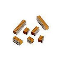
CAP CER 100UF 25V STACKED SMD
Manufacturer
AVX Corporation
Series
TurboCap™r
Specifications of ST203C107MAJ05
Capacitance
100µF
Tolerance
±20%
Temperature Coefficient
X7R
Voltage - Rated
25V
Mounting Type
Surface Mount, MLCC
Operating Temperature
-55°C ~ 125°C
Features
Stacked
Applications
Filtering Switch Mode Power Supplies
Package / Case
10-Stacked SMD, J-Lead
Size / Dimension
0.525" L x 0.300" W (13.34mm x 7.62mm)
Thickness
5.59mm Max
Lead Style
J-Lead
Voltage Rating
25 Volts
Operating Temperature Range
- 55 C to + 125 C
Product
General Type MLCCs
Dielectric Characteristic
X7R
Capacitance Tolerance
± 20%
Capacitor Case Style
DIP
No. Of Pins
10
Capacitor Mounting
SMD
Rohs Compliant
No
Termination Style
Radial
Lead Spacing
6.35 mm
Dimensions
7.62 mm W x 13.34 mm L x 5.59 mm H
Dissipation Factor Df
2.5
Lead Free Status / RoHS Status
Contains lead / RoHS non-compliant
Ratings
-
Lead Spacing
-
Lead Free Status / RoHS Status
Contains lead / RoHS non-compliant
Other names
478-6116


SMPS Capacitors (RH Style)
RH - Surface Mount ‘J’ Lead Range
ELECTRICAL SPECIFICATIONS
Temperature Coefficient CECC 30 000, (4.24.1)
X7R: C Temperature Characteristic - ± 15%, -55ºC to +125ºC
Capacitance Test
Measured at 1 VRMS max at 1KHz
Dissipation Factor 25°C
2.5% max at 1KHz, 1 VRMS max
Insulation Resistance 25°C
100K megohms or 1000 megohms-μF, whichever is less
Dielectric Withstanding Voltage 25°C (Flash Test)
250% rated voltage for 5 seconds with 50 mA max
charging current. (500 Volt units @ 150% rated voltage)
Life Test (1000 hrs) CECC 30 000 (4.23)
200% rated voltage at +125ºC.
(500 Volt units @ 120% rated voltage)
Thermal Shock IEC 68.2.14
-55ºC to +125ºC, 5 cycles
Resistance to Solder Heat IEC 68.2.20
DIMENSIONS
h
0.25 (0.010)Typ.
millimeters (inches)
L Max.
H Max.
Bend Radius
90° ±5°
2.54 (0.100)
±0.05 (0.002)
Non-Accum.
W Max.
S
This range of uncoated MLC capacitors are processed for
input and output filter capacitors in high frequency DC-DC
convertor applications above 10 Watts e.g. telecomms and
instrumentation, where high volume and low cost is required.
These products are available in surface mount ‘J’ leaded
versions and can be supplied in bulk and tape/reel packaging.
DIMENSIONS
Style
ESR @ 100KHz
ESR @ 500KHz
ESR @ 1MHz
RH21
RH22
RH31
RH32
RH41
RH42
RH51
RH52
RH61
RH62
0.047 μF to 47.0 μF
25V to 500 VDC
-55ºC to +125ºC
7.62 (0.300) 5.40 (0.213) 4.60 (0.181) 2.50 (0.098)
7.62 (0.300) 5.40 (0.213) 7.50 (0.295) 2.50 (0.098)
7.62 (0.300) 7.00 (0.270) 5.08 (0.200) 5.08 (0.200)
7.62 (0.300) 7.00 (0.270) 8.13 (0.320) 5.08 (0.200)
9.20 (0.362) 8.70 (0.342) 4.90 (0.192) 5.08 (0.200)
9.20 (0.362) 8.70 (0.342) 8.20 (0.323) 5.08 (0.200)
10.7 (0.421) 10.7 (0.421) 4.90 (0.192) 7.62 (0.300)
10.7 (0.421) 10.7 (0.421) 8.20 (0.323) 7.62 (0.300)
14.9 (0.586) 13.6 (0.535) 4.90 (0.192) 10.2 (0.400)
14.9 (0.586) 13.6 (0.535) 8.20 (0.323) 10.2 (0.400)
L max
1.4 (0.055) Typ.
0.6 (0.024)
±0.1 (0.004)
Typical ESR (mΩ) 3 μF, 100V X7R
W max
H max
Low ESR/ESL
X7R Dielectric
1.65 (0.065) ±0.15 (0.006)
(±0.004)
S ± 0.1
millimeters (inches)
(0.059 ±0.012)
(0.070 ±0.010)
(0.070 ±0.010)
(0.062 ±0.004)
(0.062 ±0.004)
(0.062 ±0.004)
(0.059 ±0.012)
(0.062 ±0.004)
(0.062 ±0.004)
(0.062 ±0.004)
1.50 ±0.30
1.50 ±0.30
1.78 ±0.25
1.78 ±0.25
1.60 ±0.10
1.60 ±0.10
1.60 ±0.10
1.60 ±0.10
1.60 ±0.10
1.60 ±0.10
M1
M1 = M2 ±0.5 (0.020)
M2
h
No. of leads
per side
17
12
14
2
2
3
3
3
3
4
4
5
5
51
Related parts for ST203C107MAJ05
Image
Part Number
Description
Manufacturer
Datasheet
Request
R

Part Number:
Description:
Inverter Grade Thyristors
Manufacturer:
International Rectifier Corp.
Datasheet:

Part Number:
Description:
Manufacturer:
AVX Corporation
Datasheet:
Part Number:
Description:
Manufacturer:
AVX Corporation
Datasheet:
Part Number:
Description:
Manufacturer:
AVX Corporation
Datasheet:
Part Number:
Description:
Manufacturer:
AVX Corporation
Datasheet: