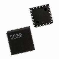
P87C591VFA/00,512 NXP Semiconductors, P87C591VFA/00,512 Datasheet - Page 19

P87C591VFA/00,512
Manufacturer Part Number
P87C591VFA/00,512
Description
IC 80C51 MCU 16K OTP 44-PLCC
Manufacturer
NXP Semiconductors
Series
87Cr
Datasheet
1.P87C591VFA00512.pdf
(160 pages)
Specifications of P87C591VFA/00,512
Core Processor
8051
Core Size
8-Bit
Speed
12MHz
Connectivity
CAN, EBI/EMI, I²C, UART/USART
Peripherals
POR, PWM, WDT
Number Of I /o
32
Program Memory Size
16KB (16K x 8)
Program Memory Type
OTP
Ram Size
512 x 8
Voltage - Supply (vcc/vdd)
4.75 V ~ 5.25 V
Data Converters
A/D 6x10b
Oscillator Type
Internal
Operating Temperature
-40°C ~ 85°C
Package / Case
44-PLCC
Processor Series
P87C5x
Core
80C51
Data Bus Width
8 bit
Data Ram Size
512 B
Interface Type
CAN, I2C, UART
Maximum Clock Frequency
12 MHz
Number Of Programmable I/os
32
Number Of Timers
3
Maximum Operating Temperature
+ 85 C
Mounting Style
SMD/SMT
3rd Party Development Tools
PK51, CA51, A51, ULINK2
Minimum Operating Temperature
- 40 C
On-chip Adc
10 bit, 6 Channel
Lead Free Status / RoHS Status
Lead free / RoHS Compliant
Eeprom Size
-
Lead Free Status / Rohs Status
Details
Other names
568-1256-5
935268182512
P87C591VFAA
935268182512
P87C591VFAA
Available stocks
Company
Part Number
Manufacturer
Quantity
Price
Company:
Part Number:
P87C591VFA/00,512
Manufacturer:
TI
Quantity:
8
Company:
Part Number:
P87C591VFA/00,512
Manufacturer:
NXP Semiconductors
Quantity:
10 000
Philips Semiconductors
7.4
The dual DPTR structure (see Figure 7) is a way by which
the chip will specify the address of an external data
memory location. There are two 16-bit DPTR registers that
address the external memory, and a single bit called DPS
= AUXR1/bit0 that allows the program code to switch
between them.
The DPS bit status should be saved by software when
switching between DPTR0 and DPTR1.
Note that bit 2 is not writable and is always read as a zero.
This allows the DPS bit to be quickly toggled simply by
executing an INC AUXR1 instruction without affecting the
other bits.
DPTR Instructions
The instructions that refer to DPTR refer to the data pointer
that is currently selected using the AUXR1/bit 0 register.
The six instructions that use the DPTR are as follows:
2000 Jul 26
handbook, full pagewidth
Single-chip 8-bit microcontroller with CAN controller
Dual DPTR
AUXR1
DPS
BT0
(83H)
DPH
(82H)
DPL
Fig.7 Dual DPTR:
DPTR1
DPTR0
19
The data pointer can be accessed on a byte-by-byte basis
by specifying the low or high byte in an instruction which
accesses the SFRs. See application note AN458 for more
details.
INC DPTRIncrements the data pointer by 1
MCV DPTR, #data 16
constant
MOV A, @ A+DPTR
MOVX A, @ DPTR
MOVX @ DPTR, A
JMP @ A + DPTR
EXTERNAL
MEMORY
DATA
MHI007
Loads the DPTR with a 16-bit
Move code byte relative to
DPTR to ACC
Move external RAM (16-bit
address) to ACC
Move ACC to external RAM
(16-bit address)
Jump indirect relative to
DPTR
Preliminary Specification
P8xC591


