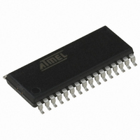
AT90PWM3-16SQ Atmel, AT90PWM3-16SQ Datasheet - Page 210

AT90PWM3-16SQ
Manufacturer Part Number
AT90PWM3-16SQ
Description
IC AVR MCU FLASH 8K 32SOIC
Manufacturer
Atmel
Series
AVR® 90PWM Lightingr
Datasheet
1.AT90PWM3B-16SU.pdf
(361 pages)
Specifications of AT90PWM3-16SQ
Core Processor
AVR
Core Size
8-Bit
Speed
16MHz
Connectivity
SPI, UART/USART
Peripherals
Brown-out Detect/Reset, POR, PWM, WDT
Number Of I /o
27
Program Memory Size
8KB (8K x 8)
Program Memory Type
FLASH
Eeprom Size
512 x 8
Ram Size
512 x 8
Voltage - Supply (vcc/vdd)
2.7 V ~ 5.5 V
Data Converters
A/D 11x10b; D/A 1x10b
Oscillator Type
Internal
Operating Temperature
-40°C ~ 105°C
Package / Case
32-SOIC (7.5mm Width)
Processor Series
AT90PWMx
Core
AVR8
Data Bus Width
8 bit
Data Ram Size
512 B
Interface Type
SPI, USART
Maximum Clock Frequency
16 MHz
Number Of Programmable I/os
27
Number Of Timers
2
Operating Supply Voltage
2.7 V to 5.5 V
Maximum Operating Temperature
+ 105 C
Mounting Style
SMD/SMT
3rd Party Development Tools
EWAVR, EWAVR-BL
Development Tools By Supplier
ATAVRDRAGON, ATSTK500, ATSTK600, ATAVRISP2, ATAVRONEKIT, ATAVRFBKIT, ATAVRISP2
Minimum Operating Temperature
- 40 C
On-chip Adc
10 bit, 11 Channel
On-chip Dac
10 bit, 1 Channel
For Use With
ATSTK600-SOIC - STK600 SOCKET/ADAPTER FOR SOICATAVRMC200 - KIT EVAL FOR AT90PWM3 ASYNCATAVRFBKIT - KIT DEMO BALLAST FOR AT90PWM2ATSTK520 - ADAPTER KIT FOR 90PWM
Lead Free Status / RoHS Status
Lead free / RoHS Compliant
- Current page: 210 of 361
- Download datasheet (7Mb)
Table 18-12. Examples of UBRR Settings for Commonly Frequencies (Continued)
1.
19. EUSART (Extended USART)
19.1
19.2
210
Baud
Rate
(bps)
2400
4800
9600
14.4k
19.2k
28.8k
38.4k
57.6k
76.8k
115.2k
230.4k
250k
500k
1M
Max.
(1)
UBRR = 0, Error = 0.0%
Features
Overview
AT90PWM2/3/2B/3B
UBRR
312
155
77
51
38
25
19
12
9
6
2
2
–
–
750 kbps
U2X = 0
f
clk
Error
11.3%
-0.2%
-2.5%
-2.7%
-8.9%
0.2%
0.2%
0.2%
0.2%
0.2%
0.2%
0.0%
io
–
–
= 12.0000 MHz
The Extended Universal Synchronous and Asynchronous serial Receiver and Transmitter
(EUSART) provides functionnal extensions to the USART.
•
•
•
•
•
A simplified block diagram of the EUSART Transmitter is shown in
I/O Registers and I/O pins are shown in bold.
Figure 19-1. EUSART Block Diagram
The EUSART is activated with the EUSART bit of EUCSRB register. Until this bit is not set, the
USART will behave as standard USART, all the functionnalities of the EUSART are not
accessible.
The EUSART supports more serial frame formats than the standard USART interface:
Independant bit number configuration for transmit and receive
Supports Serial Frames with 5, 6, 7, 8, 9 or 13, 14, 15, 16, 17 Data Bits and 1 or 2 Stop Bits
Biphase Manchester encoder/decoder (for DALI Communications)
Manchester framing error detection
Bit ordering (MSB first or LSB first)
UBRR
624
312
155
103
77
51
38
25
19
12
6
5
2
–
1.5 Mbps
U2X = 1
Error
-0.2%
-2.5%
-8.9%
0.0%
0.2%
0.2%
0.2%
0.2%
0.2%
0.2%
0.2%
0.0%
0.0%
–
UBRR
383
191
95
63
47
31
23
15
11
7
3
3
1
0
921.6 kbps
U2X = 0
f
clk
Error
-7.8%
-7.8%
-7.8%
0.0%
0.0%
0.0%
0.0%
0.0%
0.0%
0.0%
0.0%
0.0%
0.0%
0.0%
io
= 14.7456 MHz
UBRR
767
383
191
127
95
63
47
31
23
15
1.8432 Mbps
7
6
3
1
U2X = 1
Error
-7.8%
-7.8%
0.0%
0.0%
0.0%
0.0%
0.0%
0.0%
0.0%
0.0%
0.0%
0.0%
0.0%
5.3%
UBRR
416
207
103
68
51
34
25
16
12
8
3
3
1
0
U2X = 0
1 Mbps
Figure
f
clk
Error
-0.1%
-0.8%
-3.5%
0.2%
0.2%
0.6%
0.2%
0.2%
2.1%
0.2%
8.5%
0.0%
0.0%
0.0%
io
= 16.0000 MHz
19-1. CPU accessible
UBRR
832
416
207
138
103
68
51
34
25
16
8
7
3
1
4317J–AVR–08/10
U2X = 1
2 Mbps
Error
-0.1%
-0.1%
-0.8%
-3.5%
0.0%
0.2%
0.2%
0.6%
0.2%
0.2%
2.1%
0.0%
0.0%
0.0%
Related parts for AT90PWM3-16SQ
Image
Part Number
Description
Manufacturer
Datasheet
Request
R

Part Number:
Description:
IC AVR MCU FLASH 8K 32QFN
Manufacturer:
Atmel
Datasheet:

Part Number:
Description:
MCU AVR 8K FLASH 16MHZ 32-QFN
Manufacturer:
Atmel
Datasheet:

Part Number:
Description:
DEV KIT FOR AVR/AVR32
Manufacturer:
Atmel
Datasheet:

Part Number:
Description:
INTERVAL AND WIPE/WASH WIPER CONTROL IC WITH DELAY
Manufacturer:
ATMEL Corporation
Datasheet:

Part Number:
Description:
Low-Voltage Voice-Switched IC for Hands-Free Operation
Manufacturer:
ATMEL Corporation
Datasheet:

Part Number:
Description:
MONOLITHIC INTEGRATED FEATUREPHONE CIRCUIT
Manufacturer:
ATMEL Corporation
Datasheet:

Part Number:
Description:
AM-FM Receiver IC U4255BM-M
Manufacturer:
ATMEL Corporation
Datasheet:

Part Number:
Description:
Monolithic Integrated Feature Phone Circuit
Manufacturer:
ATMEL Corporation
Datasheet:

Part Number:
Description:
Multistandard Video-IF and Quasi Parallel Sound Processing
Manufacturer:
ATMEL Corporation
Datasheet:

Part Number:
Description:
High-performance EE PLD
Manufacturer:
ATMEL Corporation
Datasheet:

Part Number:
Description:
8-bit Flash Microcontroller
Manufacturer:
ATMEL Corporation
Datasheet:

Part Number:
Description:
2-Wire Serial EEPROM
Manufacturer:
ATMEL Corporation
Datasheet:


