HD6473258P10V Renesas Electronics America, HD6473258P10V Datasheet - Page 184
HD6473258P10V
Manufacturer Part Number
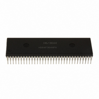
HD6473258P10V
Description
MCU 5V 32K PB-FREE 64-DIP
Manufacturer
Renesas Electronics America
Series
H8® H8/325r
Specifications of HD6473258P10V
Core Size
8-Bit
Program Memory Size
32KB (32K x 8)
Oscillator Type
External
Core Processor
H8/300
Speed
10MHz
Connectivity
SCI, UART/USART
Number Of I /o
53
Program Memory Type
OTP
Ram Size
1K x 8
Voltage - Supply (vcc/vdd)
4.5 V ~ 5.5 V
Operating Temperature
-20°C ~ 75°C
Package / Case
64-DIP
No. Of I/o's
53
Ram Memory Size
1024Byte
Cpu Speed
10MHz
No. Of Timers
3
Digital Ic Case Style
DIP
Supply Voltage
RoHS Compliant
Controller Family/series
H8/330
Rohs Compliant
Yes
Lead Free Status / RoHS Status
Lead free / RoHS Compliant
Eeprom Size
-
Data Converters
-
Peripherals
-
Lead Free Status / RoHS Status
Lead free / RoHS Compliant
Available stocks
Company
Part Number
Manufacturer
Quantity
Price
Company:

Part Number:
HD6473258P10V
Manufacturer:
RENESAS
Quantity:
600
Part Number:
HD6473258P10V
Manufacturer:
HITACHI/日立
Quantity:
20 000


9.2.7 Serial Status Register (SSR) – H’FFDC
Bit
Initial value
Read/Write
* Software can write a 0 to clear the flags, but cannot write a 1 in these bits.
The SSR is an 8-bit register that indicates transmit and receive status. It is initialized to H’87 at a
reset and in the standby modes.
Bit 7 – Transmit Data Register Empty (TDRE): This bit indicates when the TDR contents have
been transferred to the TSR and the next character can safely be written in the TDR.
Bit 7
TDRE
Bit 6 – Receive Data Register Full (RDRF): This bit indicates when one character has been
received and transferred to the RDR.
Bit 6
RDRF
0
1
0
1
Description
This bit is set to 1 at the following times:
(1)
(2)
Description
To clear RDRF, the CPU must read RDRF after
it has been set to 1, then write a 0 in this bit.
This bit is set to 1 when one character is received without error and
transferred from the RSR to the RDR.
To clear TDRE, the CPU must read TDRE after it has been set to 1, then write a 0 in
this bit.
R/(W)* R/(W)* R/(W)* R/(W)* R/(W)*
TDRE
When TDR contents are transferred to the TSR.
When the TE bit in the SCR is cleared to 0.
7
1
RDRF
6
0
ORER
5
0
177
FER
4
0
PER
3
0
—
—
2
1
—
—
1
1
(Initial value)
(Initial value)
—
—
0
1
Related parts for HD6473258P10V
Image
Part Number
Description
Manufacturer
Datasheet
Request
R

Part Number:
Description:
KIT STARTER FOR M16C/29
Manufacturer:
Renesas Electronics America
Datasheet:

Part Number:
Description:
KIT STARTER FOR R8C/2D
Manufacturer:
Renesas Electronics America
Datasheet:

Part Number:
Description:
R0K33062P STARTER KIT
Manufacturer:
Renesas Electronics America
Datasheet:

Part Number:
Description:
KIT STARTER FOR R8C/23 E8A
Manufacturer:
Renesas Electronics America
Datasheet:

Part Number:
Description:
KIT STARTER FOR R8C/25
Manufacturer:
Renesas Electronics America
Datasheet:

Part Number:
Description:
KIT STARTER H8S2456 SHARPE DSPLY
Manufacturer:
Renesas Electronics America
Datasheet:

Part Number:
Description:
KIT STARTER FOR R8C38C
Manufacturer:
Renesas Electronics America
Datasheet:

Part Number:
Description:
KIT STARTER FOR R8C35C
Manufacturer:
Renesas Electronics America
Datasheet:

Part Number:
Description:
KIT STARTER FOR R8CL3AC+LCD APPS
Manufacturer:
Renesas Electronics America
Datasheet:
Part Number:
Description:
KIT STARTER FOR RX610
Manufacturer:
Renesas Electronics America
Datasheet:

Part Number:
Description:
KIT STARTER FOR R32C/118
Manufacturer:
Renesas Electronics America
Datasheet:

Part Number:
Description:
KIT DEV RSK-R8C/26-29
Manufacturer:
Renesas Electronics America
Datasheet:

Part Number:
Description:
KIT STARTER FOR SH7124
Manufacturer:
Renesas Electronics America
Datasheet:

Part Number:
Description:
KIT STARTER FOR H8SX/1622
Manufacturer:
Renesas Electronics America
Datasheet:

Part Number:
Description:
KIT DEV FOR SH7203
Manufacturer:
Renesas Electronics America
Datasheet: