AK5384VFP AKM Semiconductor Inc, AK5384VFP Datasheet
AK5384VFP
Specifications of AK5384VFP
AK5384VFP
Available stocks


Related parts for AK5384VFP


AK5384VFP Summary of contents
Page 1
The AK5384 is a 4-channel A/D Converter with wide sampling rate of 8kHz Multi-channel audio system. The AK5384 achieves high accuracy and low cost by using Enhanced dual bit techniques. The AK5384 supports master mode and TDM format. Therefore, the ...
Page 2
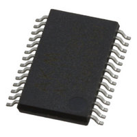
Ordering Guide AK5384VF AKD5384 n Pin Layout LIN2+ 1 LIN2- 2 RIN2+ 3 RIN2- 4 TEST 5 VCOM 6 AVSS 7 AVDD 8 DIF 9 TDM1 10 TDM0 11 TDMIN 12 MCLK 13 OVF 14 MS0225-E-00 40 +85 C ...
Page 3
ASAHI KASEI No. Pin Name I/O Function 1 LIN2+ I ADC2 Lch Positive Analog Input Pin 2 I ADC2 Lch Negative Analog Input Pin LIN2 3 RIN2+ I ADC2 Rch Positive Analog Input Pin 4 I ADC2 Rch Negative Analog ...
Page 4
DVSS=0V; Note 1) Parameter Power Supplies: Analog Digital Output buffer |AVSS – DVSS| Input Current, Any Pin Except Supplies Analog Input Voltage Digital Input Voltage (Except BICK, LRCK pins) (BICK, LRCK pins) Ambient Temperature (Powered applied) Storage Temperature Note ...
Page 5
ASAHI KASEI (Ta=25 C; AVDD=DVDD=TVDD=5.0V; AVSS=DVSS=0V; fs=48kHz, 96kHz; I/F format=Mode 0; Signal Frequency=1kHz; Measurement frequency=20Hz 20kHz at fs=48kHz, 40Hz 40kHz at fs=96kHz; unless otherwise specified) Parameter ADC Analog Input Characteristics: Resolution S/(N+D) ( 1dBFS) fs=48kHz fs=96kHz DR ( 60dBFS) fs=48kHz, ...
Page 6
ASAHI KASEI FILTER CHARACTERISTICS (fs=48kHz) (Ta=25 C; AVDD, DVDD=4.75 5.25V; TVDD=3.0 5.25V; fs=48kHz) Parameter ADC Digital Filter (Decimation LPF): Passband (Note 8) 0.005dB 0.02dB 0.06dB 6.0dB Stopband (Note 8) Passband Ripple Stopband Attenuation Group Delay (Note 9) Group Delay Distortion ...
Page 7
ASAHI KASEI (Ta=25 C; AVDD, DVDD=4.75 5.25V; TVDD=3.0 5.25V; C Parameter Master Clock Timing Master Clock 256fs: Pulse Width Low Pulse Width High 384fs: Pulse Width Low Pulse Width High 512fs: Pulse Width Low Pulse Width High 768fs: Pulse Width ...
Page 8
ASAHI KASEI Parameter Audio Interface Timing (Slave mode) Normal mode (TDM1=“L”, TDM0=“L”) BICK Period BICK Pulse Width Low Pulse Width High LRCK Edge to BICK “ ” BICK “ ” to LRCK Edge LRCK to SDTO1/2 (MSB) (Except I BICK ...
Page 9
ASAHI KASEI n Timing Diagram MCLK LRCK BICK MCLK LRCK BICK MS0225-E-00 1/fCLK tCLKH tCLKL 1/fs tBCK tBCKH tBCKL Clock Timing (TDM0 pin = “L”) 1/fCLK tCLKH tCLKL 1/fs tLRH tLRL tBCK tBCKH tBCKL Clock Timing (TDM0 pin = “H”) ...
Page 10
ASAHI KASEI LRCK tBLR BICK tLRS SDTO Audio Interface Timing (Slave mode, TDM0 pin = “L”) LRCK tBLR BICK SDTO Audio Interface Timing (Slave mode, TDM0 pin = “H”) Note: SDTO shows SDTO1 and SDTO2. MS0225-E-00 tLRB tBSD tLRB tBSD ...
Page 11
LRCK tMBLR BICK SDTO PDN SDTO PDN Note: SDTO shows SDTO1 and SDTO2. MS0225-E-00 dBCK tBSD Audio Interface Timing (Master mode) tPDV tPD Power Down & Reset Timing - 11 - 50%TVDD 50%TVDD 50%TVDD VIH VIL 50%TVDD VIL 2003/05 ...
Page 12
System Clock The external clocks which are required to operate the AK5384 are MCLK(256fs/384fs/512fs/768fs), BICK(48fs ), LRCK(1fs) in slave mode (M/S pin = “L”). MCLK should be synchronized with LRCK but the phase is not critical. When 384fs, 512fs ...
Page 13
ASAHI KASEI Mode TDM1 TDM0 0 1 Normal TDM256 TDM128 N LRCK BICK(64fs) SDTO1/2( ...
Page 14
LRCK (Mode 7) LRCK (Mode5) BICK (256fs) SDTO1 BICK Figure 4. Mode 5, 7 Timing (TDM256 mode, I LRCK (Mode 10) LRCK (Mode 8) BICK (128fs) SDTO1 23 22 Figure 5. Mode 8, 10 Timing (TDM128 ...
Page 15
ASAHI KASEI n Digital High Pass Filter The ADC has a digital high pass filter for DC offset cancellation. The cut-off frequency of the HPF is 1.0Hz(@fs=48kHz) and scales with sampling rate (fs). n Overflow Detection The AK5384 has overflow ...
Page 16
ASAHI KASEI n Cascade TDM Mode The AK5384 supports cascading two devices in a daisy chain configuration at TDM256 mode. In this mode, SDTO2 pin of device #1 is connected to TDMIN pin of device #2. SDTO1 ...
Page 17
ASAHI KASEI Figure 10 shows the system connection diagram. An evaluation board is available which demonstrates application circuits, the optimum layout, power supply arrangements and measurement results. 0.1 2.2 0.1 10 Analog Supply 4.75 ~ 5.25V TDMIN ...
Page 18
ASAHI KASEI 1. Grounding and Power Supply Decoupling The AK5384 requires careful attention to power supply and grounding arrangements. AVDD and DVDD are usually supplied from the analog supply in the system. Alternatively if AVDD and DVDD are supplied separately, ...
Page 19
ASAHI KASEI 4. External Analog Inputs Circuit Figure 11 shows an input buffer circuit example 1. The input level of this circuit is 5.7Vpp (AK5384: typ. 2.9Vpp). Analog In 5.7Vpp 10k 22 VA Bias 10k 0.1 10 Bias 10k Figure ...
Page 20
ASAHI KASEI 28pin VSOP (Unit: mm) *9.8 0.2 0.675 28 1 0.22 0.1 Seating Plane NOTE: Dimension "*" does not include mold flash. n Material & Lead finish Package molding compound: Lead frame material: Lead frame surface treatment: MS0225-E-00 PACKAGE ...
Page 21
XXXB : Lot number (X : Digit number Alpha character) YYYYC : Assembly date (Y : Digit number Alpha character) These products and their specifications are subject to change without notice. Before considering any use or ...