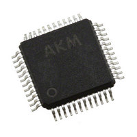
AK4358VQ AKM Semiconductor Inc, AK4358VQ Datasheet - Page 13

AK4358VQ
Manufacturer Part Number
AK4358VQ
Description
IC DAC 24BIT SERIAL 48LQFP
Manufacturer
AKM Semiconductor Inc
Datasheet
1.AK4358VQ.pdf
(36 pages)
Specifications of AK4358VQ
Number Of Bits
24
Data Interface
I²S, Serial
Number Of Converters
8
Voltage Supply Source
Analog and Digital
Operating Temperature
-40°C ~ 85°C
Mounting Type
Surface Mount
Package / Case
48-LFQFP
Lead Free Status / RoHS Status
Lead free / RoHS Compliant
Power Dissipation (max)
-
Settling Time
-
Other names
974-1008-2
Available stocks
Company
Part Number
Manufacturer
Quantity
Price
Company:
Part Number:
AK4358VQ
Manufacturer:
AKM Semiconductor Inc
Quantity:
1 951
Company:
Part Number:
AK4358VQ
Manufacturer:
AKM
Quantity:
11 050
Company:
Part Number:
AK4358VQ-L
Manufacturer:
ELPIDA
Quantity:
32
Part Number:
AK4358VQ-L
Manufacturer:
AKM
Quantity:
20 000
Company:
Part Number:
AK4358VQP-L
Manufacturer:
AKM Semiconductor Inc
Quantity:
10 000
■
The AK4358 can perform D/A conversion for both PCM data and DSD data. When DSD mode, DSD data can be input
from DCLK, DSDL1-4 and DSDR1-4 pins. When PCM mode, PCM data can be input from BICK, SDTI1-4 and LRCK
pins. PCM/DSD mode changes by D/P bit. When PCM/DSD mode changes by D/P bit, the AK4358 should be reset by
RSTN bit, PW bit (PW1=PW2=PW3=PW4= “0”) or PDN pin. It takes about 2/fs to 3/fs to change the mode.
■
1) PCM Mode
The external clocks, which are required to operate the AK4358, are MCLK, LRCK and BICK. The master clock (MCLK)
should be synchronized with LRCK but the phase is not critical. The MCLK is used to operate the digital interpolation
filter and the delta-sigma modulator. There are two methods to set MCLK frequency. In Manual Setting Mode (ACKS =
“0”: Register 00H), the sampling speed is set by
automatically.
automatically
set DFS0/1. When ACKSN = “H”, regardless of ACKS bit setting the AK4358 operates by Manual Setting Mode. When
ACKSN = “L”, ACKS bit setting is valid.
All external clocks (MCLK, BICK and LRCK) should always be present whenever the AK4358 is in the normal operation
mode (PDN= “H”). If these clocks are not provided, the AK4358 may draw excess current and may fall into unpredictable
operation. This is because the device utilizes dynamic refreshed logic internally. The AK4358 should be reset by PDN =
“L” after threse clocks are provided. If the external clocks are not present, the AK4358 should be in the power-down
mode (PDN= ”L”). After exiting reset(PDN = “↑”) at power-up etc., the AK4358 is in the power-down mode until MCLK
is input. DSD interface signals (DCLK, DSDL1-4, DSDR1-4) are fixed to “H” or “L”.
MS0203-E-02
D/A Conversion Mode
System Clock
(Table
32.0kHz
44.1kHz
48.0kHz
(Table 3~Table
LRCK
fs
Table 3. System Clock Example (Normal Speed Mode @Manual Setting Mode)
6), and the internal master clock becomes the appropriate frequency
11.2896MHz 16.9344MHz 22.5792MHz 33.8688MHz
12.2880MHz 18.4320MHz 24.5760MHz 36.8640MHz
8.1920MHz 12.2880MHz 16.3840MHz 24.5760MHz
DFS1
0
0
1
256fs
5). In Auto Setting Mode (ACKS = “1”: Default), as MCLK frequency is detected
Table 2. Sampling Speed (Manual Setting Mode)
DFS0
0
1
0
Table 1. DSD/PCM Mode Control
OPERATION OVERVIEW
D/P bit
0
1
384fs
Normal Speed Mode
Double Speed Mode
Quad Speed Mode
DFS0/1(Table
MCLK
- 13 -
DAC Output
PCM
DSD
512fs
Sampling Rate (fs)
2). The frequency of MCLK at each sampling speed is set
120kHz~192kHz
60kHz~96kHz
768fs
8kHz~48kHz
(Table
2.0480MHz
2.8224MHz
3.0720MHz
BICK
64fs
7), it is not necessary to
Default
[AK4358]
2009/05


