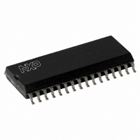
MFRC50001T/0FE,112 NXP Semiconductors, MFRC50001T/0FE,112 Datasheet - Page 33

MFRC50001T/0FE,112
Manufacturer Part Number
MFRC50001T/0FE,112
Description
IC MIFARE READER 32-SOIC
Manufacturer
NXP Semiconductors
Series
MIFARE®r
Specifications of MFRC50001T/0FE,112
Rf Type
Read Only
Frequency
13.56MHz
Features
ISO14443-A, ISO14443-B, ISO15693
Package / Case
32-SOIC (0.300", 7.50mm Width)
Product
RFID Readers
Operating Temperature Range
- 25 C to + 85 C
Lead Free Status / RoHS Status
Lead free / RoHS Compliant
Lead Free Status / RoHS Status
Lead free / RoHS Compliant, Lead free / RoHS Compliant
Other names
568-2222-5
935268039112
MFRC500
MFRC51T0FED
935268039112
MFRC500
MFRC51T0FED
Available stocks
Company
Part Number
Manufacturer
Quantity
Price
Part Number:
MFRC50001T/0FE,112
Manufacturer:
NXP/恩智浦
Quantity:
20 000
NXP Semiconductors
MFRC500_33
Product data sheet
PUBLIC
Fig 12. Serial signal switch block diagram
serial data out
serial data in
serial data processing
(part of)
9.11.1 Serial signal switch block diagram
MILLER CODER
MANCHESTER
1 OUT OF 256
9.11 Serial signal switch
1 OUT OF 4
DECODER
SERIAL SIGNAL SWITCH
NRZ OR
Remark: It is recommended to use the Q-clock.
The MFRC500 comprises two main blocks:
The interface between these two blocks can be configured so that the interface signals
are routed to pins MFIN and MFOUT. This makes it possible to connect the analog part of
one MFRC500 to the digital part of another device.
Figure 12
the serial signal switch enabling the MFRC500 to be used in different configurations.
The serial signal switch can also be used to check the transmitted and received data
during the design-in phase or for test purposes.
analog test signals and measurements at the serial signal switch.
Remark: The SLR400 uses pin name SIGOUT for pin MFOUT. The MFRC500
functionality includes the test modes for the SLRC400 using pin MFOUT.
•
•
Source[1:0]
digital circuitry: comprising the state machines, encoder and decoder logic etc.
analog circuitry: comprising the modulator, antenna drivers, receiver and
amplification circuitry
Decoder
2
0
1
2
3
shows the serial signal switches. Three different switches are implemented in
0
internal
Manchester with subcarrier
Manchester
All information provided in this document is subject to legal disclaimers.
DEMODULATOR
SUBCARRIER
Rev. 3.3 — 15 March 2010
MFIN
048033
MFOUT
0
envelope
1
MFIN
Highly Integrated ISO/IEC 14443 A Reader IC
0
1
digital test signal
signal to MFOUT
Manchester out
Source[1:0]
0
1
2
3
Modulator
2
Section 15.2.1 on page 94
3
MFOUTSelect[2:0]
DEMODULATOR
SUBCARRIER
MODULATOR
analog circuitry
(part of)
MFRC500
DEMODULATOR
© NXP B.V. 2010. All rights reserved.
CARRIER
DRIVER
describes the
001aak617
33 of 110
TX1
TX2
RX


