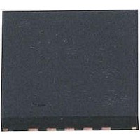
AT42QT1070-MMH Atmel, AT42QT1070-MMH Datasheet - Page 15

AT42QT1070-MMH
Manufacturer Part Number
AT42QT1070-MMH
Description
IC TOUCH SENSOR 7KEY 20-VQFN
Manufacturer
Atmel
Type
Capacitiver
Specifications of AT42QT1070-MMH
Number Of Inputs/keys
7 Key (Comms), 5 Key (Standalone)
Data Interface
I²C
Voltage Reference
Internal
Voltage - Supply
1.8 V ~ 5.5 V
Operating Temperature
-40°C ~ 85°C
Mounting Type
Surface Mount
Package / Case
20-VFQFN Exposed Pad
Supply Voltage
1.8 V to 5.5 V
Dimensions
3 mm L x 3 mm W x 0.8 mm H
Temperature Range
- 40 C to + 85 C
Termination Style
SMD/SMT
Lead Free Status / RoHS Status
Lead free / RoHS Compliant
Current - Supply
-
Resolution (bits)
-
Touch Panel Interface
-
Data Rate/sampling Rate (sps, Bps)
-
Lead Free Status / Rohs Status
Lead free / RoHS Compliant
Available stocks
Company
Part Number
Manufacturer
Quantity
Price
Company:
Part Number:
AT42QT1070-MMH QS529
Manufacturer:
Atmel
Quantity:
9 390
2.3.3
Touch Sensors Design Guide
Front Panel Materials
It is acceptable to use a flex PCB or FFC/FPC
certain that it will be mechanically stable for the intended uses of the product. The traces running in the
flex will be part of the touch sensor; so if the flex shifts even a fraction of a millimeter, the capacitance to
its surroundings will definitely change and might be significant, causing false touches or drops in
sensitivity. Running the flex in close proximity to a metal chassis or other signals, or over the top of noisy
circuitry, can cause problems too.
Common front panel materials include glass, plexiglas, polycarbonate and PMMA. Remember that glass
front panels may require an anti-shatter layer to pass drop and safety tests; this is often an extra PET film
bonded to the glass. In general, the same rules apply to front panels as apply to substrates but, of
course, a common requirement is to also offer excellent transparency and cosmetic quality.
The panel thickness and its dielectric constant (
field at the surface of the control panel. If the metal electrodes are on the inside surface of the substrate,
then the thickness and
Glass has a higher
propagate through more effectively. Thus a 5 mm panel with an
to a 2.5 mm panel with an epsilon of 4, all other factors being equal.
A plastic panel up to 10 mm thick is quite usable, depending on key spacing and size. The circuit
sensitivity needs to be adjusted during development to compensate for panel thickness, dielectric
constant and electrode size.
The thicker a given material is, the worse the SNR. For this reason, it is always better to try and reduce
the thickness of the front panel material. Materials with high relative dielectric constants are also
preferable for front panels as they help to increase SNR.
Table 2-1. Relative Dielectric Constants for Materials
1. FFC = Flat Flexible Conductor, FPC = Flexible Printed Circuit
Material
Vacuum
Air
Glass
Sapphire Glass
Mica
Nylon
Silicon
Silicone Rubber
Silicone Moulding Compound
Paper
Plexiglas
Polycarbonate
Polyethylene
Polystyrene
PET (Polyethylene Terephthalate)
r
than most plastics (see Table 2-1). Higher numbers mean that the fields will
r
of the substrate are also factors.
(1)
r
) play a large part in determining the strength of electric
Dielectric Constant (
1 (by definition)
1.00059
3.7 to 10
9 to 11
4 to 8
3
11 to 12
3.2 to 9.8
3.7
2
3.4
2.9 to 3.0
2.2 to 2.4
2.56
3
to act as an interconnection, but make sure you are
r
of 8 will perform similarly in sensitivity
r
)
General Advice
10620D–AT42–04/09
2-5


