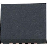
AT42QT1070-MMH Atmel, AT42QT1070-MMH Datasheet - Page 45

AT42QT1070-MMH
Manufacturer Part Number
AT42QT1070-MMH
Description
IC TOUCH SENSOR 7KEY 20-VQFN
Manufacturer
Atmel
Type
Capacitiver
Specifications of AT42QT1070-MMH
Number Of Inputs/keys
7 Key (Comms), 5 Key (Standalone)
Data Interface
I²C
Voltage Reference
Internal
Voltage - Supply
1.8 V ~ 5.5 V
Operating Temperature
-40°C ~ 85°C
Mounting Type
Surface Mount
Package / Case
20-VFQFN Exposed Pad
Supply Voltage
1.8 V to 5.5 V
Dimensions
3 mm L x 3 mm W x 0.8 mm H
Temperature Range
- 40 C to + 85 C
Termination Style
SMD/SMT
Lead Free Status / RoHS Status
Lead free / RoHS Compliant
Current - Supply
-
Resolution (bits)
-
Touch Panel Interface
-
Data Rate/sampling Rate (sps, Bps)
-
Lead Free Status / Rohs Status
Lead free / RoHS Compliant
Available stocks
Company
Part Number
Manufacturer
Quantity
Price
Company:
Part Number:
AT42QT1070-MMH QS529
Manufacturer:
Atmel
Quantity:
9 390
4.3.4
4.3.5
4.3.6
4.3.7
4.3.8
Touch Sensors Design Guide
Adapting the Planar Construction For Distribution Across Two Layers
Ground Loading
Illumination Effects
Floating Conductive Items
Conductive Paints
For completeness, it is worth noting that the planar construction detailed in
be distributed across two layers if desired; it may, for example, make the layout and interconnections
easier. Generally, try to keep the Y layer nearest to touch and avoid separating the Y and X layers
vertically by more than 10 percent of the X to Y gap.
A non-planar construction method tends to have less potential for signal loss from nearby ground loads,
and so is generally far less sensitive than a planar design. Flooded-X style sensors are particularly good
in this regard because the X drive has a low impedance. This means that it can be loaded with relatively
high amounts of parasitic capacitance before the RC time constant becomes a concern.
Generally, the considerations of
The issues for illumination are very similar to those presented in
page
electrode can be opened to make way for an LED (see
necessary to increase the diameter of the Y electrode slightly while ensuring that the surrounding ring
has the greatest width as possible.
Figure 4-13. Using an LED With a Spring In a Mutual-capacitance Type Sensor
The considerations for the use of floating conductive items described in
Conductive Items” on page 4-9
The considerations for the use of conductive paints described in
page 3-7
3-10. When considering the use of LEDs in the centre of spring-based sensors, the Y disc
apply.
apply.
Section 4.2.3 “Ground Loading” on page 4-6
Y Electrode
Mutual-capacitance Zero-dimensional Sensors
LED
Figure 4-13 on page
Section 3.3.5 “Illumination Effects” on
Section 3.2.7 “Conductive Paints” on
Section 4.2 on page 4-1
4-13). In this case it may be
X Electrode
will apply.
Section 4.2.6 “Floating
10620D–AT42–04/09
4-13
can


