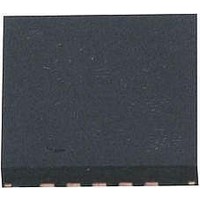
AT42QT1070-MMH Atmel, AT42QT1070-MMH Datasheet - Page 24

AT42QT1070-MMH
Manufacturer Part Number
AT42QT1070-MMH
Description
IC TOUCH SENSOR 7KEY 20-VQFN
Manufacturer
Atmel
Type
Capacitiver
Specifications of AT42QT1070-MMH
Number Of Inputs/keys
7 Key (Comms), 5 Key (Standalone)
Data Interface
I²C
Voltage Reference
Internal
Voltage - Supply
1.8 V ~ 5.5 V
Operating Temperature
-40°C ~ 85°C
Mounting Type
Surface Mount
Package / Case
20-VFQFN Exposed Pad
Supply Voltage
1.8 V to 5.5 V
Dimensions
3 mm L x 3 mm W x 0.8 mm H
Temperature Range
- 40 C to + 85 C
Termination Style
SMD/SMT
Lead Free Status / RoHS Status
Lead free / RoHS Compliant
Current - Supply
-
Resolution (bits)
-
Touch Panel Interface
-
Data Rate/sampling Rate (sps, Bps)
-
Lead Free Status / Rohs Status
Lead free / RoHS Compliant
Available stocks
Company
Part Number
Manufacturer
Quantity
Price
Company:
Part Number:
AT42QT1070-MMH QS529
Manufacturer:
Atmel
Quantity:
9 390
10620D–AT42–04/09
Self-capacitance Zero-dimensional Sensors
3.2.4
3-4
Interconnection
Figure 3-5.
While the ground flood shown in Figure 3-5 is is an effective approach, it should be remembered that
ground areas near the key also increase the capacitive loading (Cx), thereby also reducing sensitivity to
touch. Although this effect can be compensated by increasing the sample capacitor Cs, an overall
decrease in signal-to-noise ratio (SNR) and an increase in power consumption will occur.
A compromise is to place a ground ring around the electrode with a 3–5 mm gap. The electric fields will
terminate sharply across this gap yet capacitive loading on the key will be minimized. A ground plane
near an electrode will cause the key to be less sensitive near its edges, since the field lines are shunted
away from the panel surface. The width of the ground plane also matters: a thin ground track next to an
electrode will have less of an effect than a wide ground pour.
For small battery-powered devices, the addition of a ground plane can greatly aid the free-space return
path
stray interfering fields, and fields from the sensor itself, making the sensor more immune to noise and
more focused in terms of its sensitive region.
One down-side to this ground plane is that it offers a very easy path for water droplets to bridge and
cause capacitive changes that look very much like a normal touch. Therefore, for applications where
moisture sensitivity is a concern, it is best to avoid this ground plane method.
Note that, in any case, ground planes or tracks should only be used to define a key area as a last resort
for a specific purpose. Key fields will naturally decay with distance from an electrode edge, and this drop
in field strength is usually enough to define a key boundary.
This type of sensor should be connected to the controller using conductive traces that are as thin as
possible, while observing RC time constant effects. Interconnections that are shorter than 150 mm are
recommended. Longer traces can couple noise and add parasitic capacitance that reduces sensitivity.
Note that interconnecting traces are touch sensitive and simply form an extension to the sensor itself. It
is good practice to run sensor traces on a PCB or substrate layer that is farthest from touch, while the
sensor is on a layer closest to touch.
Traces from neighboring sensors should be spaced as far apart as practically possible. A good rule of
thumb is to space adjacent traces so that the gap between them is at least half the panel thickness
(T/2) – see
1. The implied return path between the person touching the product and the product itself via “free-space” (that is,
2. Assuming that these sensor traces are driven from the same chip.
the current returns via the capacitance that couples the product to the person’s body).
(1)
of the product and so actually make the sensor more sensitive overall. It also helps to control
Figure
A Ground Flood Near To a Sensor
3-6.
(2)
Sensor
Gap of at least ½T between
sensor and ground plane
Ground
Plane
Touch Sensors Design Guide


