ADNS-6010 Avago Technologies US Inc., ADNS-6010 Datasheet - Page 21
ADNS-6010
Manufacturer Part Number
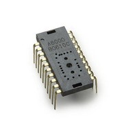
ADNS-6010
Description
Optical Sensors - Board Mount Laser mouse sensor
Manufacturer
Avago Technologies US Inc.
Datasheet
1.ADNS-6010.pdf
(41 pages)
Specifications of ADNS-6010
Lead Free Status / RoHS Status
Lead free / RoHS Compliant
Available stocks
Company
Part Number
Manufacturer
Quantity
Price


Notes on Power-up and the serial port
Reset Circuit
The ADNS-6010 does not perform an internal power up
self-reset; the reset pin must be raised and lowered to
reset the chip. This should be done every time power is
applied. During power-up there will be a period of time
after the power supply is high but before any clocks are
available. The table below shows the state of the various
pins during power-up and reset when the RESET pin is
driven high by a micro-controller.
21
Pin
SPI pullups
NCS
MISO
SCLK
MOSI
XY_LASER
RESET
NPD
LASER_NEN
Pin
SPI pullups
NCS
MISO
SCLK
MOSI
XY_LASER
RESET
NPD
REFC
OSC_IN
OSC_OUT
LASER_NEN
Before Reset
undefined
hi-Z control
functional
driven or hi-Z
(per NCS)
undefined
undefined
undefined
functional
undefined
undefined
State of Signal Pins During Power Down
State of Signal Pins After VDD is Valid
NPD low
off
hi-Z control functional
low or hi-Z (per NCS)
ignored
ignored
high (off )
functional
low (driven externally)
V
low
high
high (off )
DD3
During Reset
off
hi-Z control
functional
driven or hi-Z
(per NCS)
ignored
ignored
hi-Z
high
(externally driven)
ignored
high (off )
After wake from PD
pre-PD state
functional
pre-PD state or hi-Z
functional
functional
functional
functional
functional
REFC
OSC_IN
OSC_OUT
functional
After Reset
on (default)
functional
low or hi-Z
(per NCS)
functional
functional
functional
functional
functional
functional
Power Down Circuit
The following table lists the pin states during power
down.
The chip is put into the power down (PD) mode by low-
ering the NPD input. When in PD mode, the oscillator is
stopped but all register contents are retained. To achieve
the lowest current state, all inputs must be held exter-
nally within 200mV of a rail, either ground or VDD3. The
chip outputs are driven low or hi-Z during PD to prevent
current consumption by an external load.
Related parts for ADNS-6010
Image
Part Number
Description
Manufacturer
Datasheet
Request
R

Part Number:
Description:
Optical Mouse Sensor,DIP
Manufacturer:
Avago Technologies US Inc.
Datasheet:

Part Number:
Description:
Optical Mouse Sensor,DIP
Manufacturer:
Avago Technologies US Inc.
Datasheet:

Part Number:
Description:
Trim Lens For ADNS-3530
Manufacturer:
Avago Technologies US Inc.
Datasheet:

Part Number:
Description:
8 DIP SFF Navigation Sensor
Manufacturer:
Avago Technologies US Inc.
Datasheet:

Part Number:
Description:
Trim Lens For ADNS-5090
Manufacturer:
Avago Technologies US Inc.
Datasheet:

Part Number:
Description:
BLACK CLIP FOR ADNS-5000
Manufacturer:
Avago Technologies US Inc.
Datasheet:
Part Number:
Description:
Lens For ADNS-7630
Manufacturer:
Avago Technologies US Inc.
Datasheet:

Part Number:
Description:
Optical Mouse Sensor,DIP
Manufacturer:
Avago Technologies US Inc.
Datasheet:

Part Number:
Description:
SENSOR OPTICAL MOUSE 8-DIP
Manufacturer:
Avago Technologies US Inc.
Datasheet:
Part Number:
Description:
Optical Mouse Sensor,DIP
Manufacturer:
Avago Technologies US Inc.
Datasheet:

Part Number:
Description:
OPTOCOUPLER GATE DRV 2A 16-SOIC
Manufacturer:
Avago Technologies US Inc.
Datasheet:
Part Number:
Description:
OPTOCOUPLER 2CH 2.5A 16-SOIC
Manufacturer:
Avago Technologies US Inc.
Datasheet:

Part Number:
Description:
OPTOCOUPLER GATE DRV 0.4A 16SOIC
Manufacturer:
Avago Technologies US Inc.
Datasheet:

Part Number:
Description:
OPTOCOUPLER 2.0A 250KHZ 8-DIP
Manufacturer:
Avago Technologies US Inc.
Datasheet:

Part Number:
Description:
OPTOCOUPLER 2.0A 250KHZ GW 8-SMD
Manufacturer:
Avago Technologies US Inc.
Datasheet: