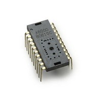
ADNS-6010 Avago Technologies US Inc., ADNS-6010 Datasheet - Page 8

ADNS-6010
Manufacturer Part Number
ADNS-6010
Description
Optical Sensors - Board Mount Laser mouse sensor
Manufacturer
Avago Technologies US Inc.
Datasheet
1.ADNS-6010.pdf
(41 pages)
Specifications of ADNS-6010
Lead Free Status / RoHS Status
Lead free / RoHS Compliant
Available stocks
Company
Part Number
Manufacturer
Quantity
Price
Notes (for Figure 7)
x Caps for pins 11, 12, 16 and 18 MUST have trace lengths LESS than
x Pins 16 and 18 caps MUST use pin 17 GND.
x Pin 9, if used, should not be connected to PCB GND to reduce po-
x The 0.1 uF caps must be ceramic.
x Caps should have less than 5 nH of self inductance.
x Caps should have less than 0.2 W ESR.
x NC pins should not be connected to any traces.
x Surface mount parts are recommended.
x Care must be taken when interfacing a 5V microcontroller to
x VDD3 and GND should have low impedance connections to the
x Because the RBIN pin sets the XY_LASER current, the following PC
8
5 mm on each side.
tential RF emissions.
the ADNS-6010. Serial port inputs on the sensor should be con-
nected to open-drain outputs from the microcontroller or use an
active drive level shifter. NPD and RESET should be connected
to 5V microcontroller outputs through a resistor divider or other
level shifting technique.
power supply.
board layout practices should be followed to reduce the chance
of uncontrolled laser drive current caused from a leakage path
between RBIN and ground. One hypothetical source of such a
leakage path is PC board contamination due to a liquid, such as a
soft drink, being deposited on the printed circuit board.
o The RBIN resistor should be located close to the sensor pin
o The pin 13 solder pad and all exposed conductors connected
o The pin 13 solder pad, the traces connected to pin 13, and the
o The RBIN resistor should be a thru-hole style to increase the
13. The traces between the resistor and the sensor should be
short.
to pin 13 should be surrounded by a guard trace connected to
VDD3 and devoid of a solder mask.
RBIN resistor should be covered with a conformal coating.
distance between its terminals. This does not apply if a confor-
mal coating is used.
RESET
MISO
MOSI
External PROM
The ADNS-6010 must operate from externally loaded
programming. This architecture enables immediate
adoption of new features and improved performance
algorithms. The external program is supplied by Avago
Technologies as a file, which may be burned into a pro-
grammable device. The example application shown in
this document uses an EEPROM to store and load the
external program memory. A micro-controller with suf-
ficient memory may be used instead. On power-up and
reset, the ADNS-6010 program is downloaded into vola-
tile memory using the burst-mode procedure described
in the Synchronous Serial Port section. The program size
is 1986 x 8 bits.
SCLK
RBIN
Figure 8. Block diagram of ADNS-6010 optical mouse sensor
NCS
CTRL
LASER DRIVER
PROCESSOR
IMAGE
OSCILLATOR
OSC_IN
OSC_OUT
REFB
REFC
NPD
GND
XY_LASER
V
LASER_NEN
DD3
3.3 V POWER
REFERENCE
VOLTAGE
FILTER NODE
RESONATOR


