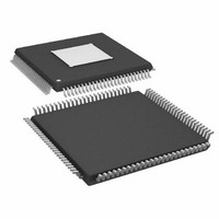
ADAU1445YSVZ-3A-RL Analog Devices Inc, ADAU1445YSVZ-3A-RL Datasheet - Page 66

ADAU1445YSVZ-3A-RL
Manufacturer Part Number
ADAU1445YSVZ-3A-RL
Description
175MHZ SigmaDSP,2x8 SRCs
Manufacturer
Analog Devices Inc
Series
SigmaDSP®r
Type
Audio Processorr
Specifications of ADAU1445YSVZ-3A-RL
Applications
Automotive Audio
Mounting Type
Surface Mount
Package / Case
100-TQFP Exposed Pad, 100-eTQFP, 100-HTQFP, 100-VQFP
Format
Fixed Point
Program Memory Size
Not RequiredKB
Operating Supply Voltage (typ)
1.8/3.3V
Operating Temp Range
-40C to 105C
Operating Temperature Classification
Industrial
Mounting
Surface Mount
Pin Count
100
Lead Free Status / RoHS Status
Lead free / RoHS Compliant
Lead Free Status / RoHS Status
Lead free / RoHS Compliant
Available stocks
Company
Part Number
Manufacturer
Quantity
Price
Company:
Part Number:
ADAU1445YSVZ-3A-RL
Manufacturer:
Analog Devices Inc
Quantity:
10 000
ADAU1445/ADAU1446
Enable S/PDIF to I
Table 62. Bit Descriptions of Register 0xE241
Bit Position
[15:3]
[2]
[1]
[0]
The S/PDIF receiver can be set to send the stereo audio stream
and the auxiliary S/PDIF bits in I
the 12 MP pins. The eight outputs are divided into two groups:
Group 1 converts S/PDIF to I
signals), and Group 2 decodes the channel status and user data
bits (virtual LRCLK, user data, channel status, validity bit, and
block start signal).
LRCLKx
Description
Reserved
Output mode
0 = I
1 = TDM
Group 2 enable
0 = Group 2 off
1 = Group 2 on
Group 1 enable
0 = Group 1 off
1 = Group 1 on
2
2
S Output Register (Address 0xE241)
S
2
LEFT AUDIO
S (LRCLK, BCLK, and SDATA
2
0
24 BITS: LEFT AUDIO
S or TDM format on eight of
DECODE BITS
1
0
2
Default
0
0
0
Figure 54. S/PDIF TDM Signal
Rev. A | Page 66 of 92
7 DECODED
BITS
3
FRAME
RIGHT AUDIO
This MP output is controlled by setting three bits in
Register 0xE241:
•
•
•
When S/PDIF to I
are used.
When TDM mode is active, Slot 0 and Slot 4 contain the audio
data, and Slot 1 contains the streamed block start, channel status,
user data, and validity bits (see Table 63). The bits are streamed
in real time and are synchronized to the audio data. Only the
seven MSBs of Slot 1 are used, as shown in Table 63. The corre-
sponding TDM format is shown in more detail in Figure 54.
Table 63. Function of Decoded Bits in Figure 54
Bit Position
[31]
[30]
[29]
[28]
[27]
[26]
[25]
[24:0]
4
1
Bit 0 switches Group 1 on and off.
Bit 1 switches Group 2 on and off.
Bit 2 switches between I
5
24 BITS: RIGHT AUDIO
2
S mode is active, the pins described in Table 51
Description
Block start (high for first 16 samples)
Channel status of right channel
Channel status of left channel
User data bit, right channel
User data bit, left channel
Validity bit, right channel
Validity bit, left channel
Not used
6
2
4
S and TDM modes.
7


