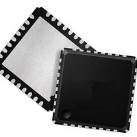
LAN88710BMR SMSC, LAN88710BMR Datasheet - Page 10

LAN88710BMR
Manufacturer Part Number
LAN88710BMR
Description
Ethernet ICs MII/RMII 10/100 Automot Transceiver
Manufacturer
SMSC
Datasheet
1.LAN88710BM_SAMPLES.pdf
(80 pages)
Specifications of LAN88710BMR
Ethernet Connection Type
10BASE-T, 100BASE-TX
Minimum Operating Temperature
- 40 C
Mounting Style
SMD/SMT
Product
Ethernet Transceivers
Standard Supported
IEEE802.3, IEEE802.3u
Supply Voltage (max)
3.6 V
Supply Voltage (min)
1.6 V
Maximum Operating Temperature
+ 105 C
Package / Case
QFN-32
Lead Free Status / RoHS Status
Lead free / RoHS Compliant
Revision 1.1 (05-26-10)
NUM PINS
1
1
1
1
1
1
1
(MII Mode)
(MII Mode)
(MII Mode)
(MII Mode)
(MII Mode)
Transmit
Transmit
Transmit
Transmit
Transmit
Transmit
Transmit
Transmit
Interrupt
Data 0
Data 1
Data 2
Data 3
Output
Data 4
Enable
NAME
Clock
Error
SYMBOL
TXCLK
TXER
TXEN
TXD0
TXD1
TXD2
TXD3
TXD4
nINT
Small Footprint MII/RMII 10/100 Ethernet Transceiver for Automotive Applications
Table 2.1 MII/RMII Signals
DATASHEET
BUFFER
TYPE
VO8
(PU)
(PU)
(PD)
VO8
VIS
VIS
VIS
VIS
VIS
VIS
VIS
10
The MAC transmits data to the transceiver using
this signal in all modes.
The MAC transmits data to the transceiver using
this signal in all modes.
The MAC transmits data to the transceiver using
this signal in MII mode.
Note:
The MAC transmits data to the transceiver using
this signal in MII mode.
Note:
Active low interrupt output. Place an external
resistor pull-up to VDDIO.
Note:
Note:
When driven high, the 4B/5B encode process
substitutes the Transmit Error code-group (/H/)
for the encoded data word. This input is ignored
in the 10BASE-T mode of operation.
In Symbol Interface (5B decoding) mode, this
signal becomes the MII Transmit Data 4 line (the
MSB of the 5-bit symbol code-group).
Note:
Indicates that valid transmission data is present
on TXD[3:0]. In RMII mode, only TXD[1:0]
provide valid data.
Used to latch data from the MAC into the
transceiver.
Note:
MII (100BASE-TX): 25 MHz
MII (10BASE-T): 2.5 MHz
This signal must be grounded in RMII
mode.
This signal must be grounded in RMII
mode.
Refer to
Management," on page 35
details on device interrupts.
Refer to
LED2 Polarity Selection," on page 42
details on how the nINTSEL
configuration strap is used to determine
the function of this pin.
This signal is not used in RMII mode.
This signal is not used in RMII mode.
DESCRIPTION
Section 3.8.1.2, "nINTSEL and
Section 3.6, "Interrupt
SMSC LAN88710AM/LAN88710BM
for additional
Datasheet
for


