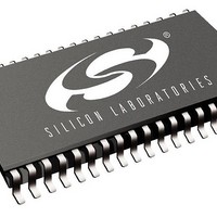
SI3210-BTR Silicon Laboratories Inc, SI3210-BTR Datasheet - Page 121

SI3210-BTR
Manufacturer Part Number
SI3210-BTR
Description
Telecom Line Management ICs Sgl Ch SLIC/Codec w/ DTMF Decoder
Manufacturer
Silicon Laboratories Inc
Datasheet
1.SI3210MPPQX-EVB.pdf
(146 pages)
Specifications of SI3210-BTR
Product
SLIC
Supply Voltage (min)
3.13 V
Supply Current
88 mA
Maximum Operating Temperature
+ 85 C
Minimum Operating Temperature
- 40 C
Mounting Style
SMD/SMT
Number Of Channels
1
Package / Case
TSSOP-38
Lead Free Status / RoHS Status
Lead free / RoHS Compliant
- Current page: 121 of 146
- Download datasheet (860Kb)
4.3. Digital Programmable Gain/Attenuation
See functional description sections of digital programmable gain/attenuation for guidelines on computing register
values. All values are represented in 2s-complement format.
Note: The values of all indirect registers are undefined following the reset state. Shaded areas denote bits that can be read
Addr.
Addr.
26
27
26
27
and written but must be written to zeroes.
Receive Path Digital to Analog Converter Gain/Attenuation.
This register sets gain/attenuation for the receive path. The digitized signal is effectively mul-
tiplied by DACG to achieve gain/attenuation. A value of 0x00 corresponds to – dB gain
(mute). A value of 0x400 corresponds to unity gain. A value of 0x7FF corresponds to a gain
of 6 dB.
Transmit Path Analog to Digital Converter Gain/Attenuation.
This register sets gain/attenuation for the transmit path. The digitized signal is effectively
multiplied by ADCG to achieve gain/attenuation. A value of 0x00 corresponds to – dB gain
(mute). A value of 0x400 corresponds to unity gain. A value of 0x7FF corresponds to a gain
of 6 dB.
D15
Table 42. Digital Programmable Gain/Attenuation Indirect Registers Description
Table 41. Digital Programmable Gain/Attenuation Indirect Registers Summary
D14
D13
D12
D11
DACG[11:0]
ADCG[11:0]
D10
Description
D9
Rev. 1.5
D8
D7
D6
D5
Si3210/Si3211
D4
D3
D2
Reference
D1
Page
48
48
D0
121
Related parts for SI3210-BTR
Image
Part Number
Description
Manufacturer
Datasheet
Request
R
Part Number:
Description:
C°/SI3210 QFN EVALUATION BOARD WITH DISCRETE LINE INTERFACE
Manufacturer:
Silicon Laboratories Inc
Datasheet:
Part Number:
Description:
QFN 38/I°/SINGLE-CHANNEL SLIC/CODEC WITH DTMF DECODER AND BJT/INDUCTOR DC-D
Manufacturer:
Silicon Laboratories Inc
Part Number:
Description:
IC SLIC/CODEC PROGRAMMBL 38TSSOP
Manufacturer:
Silicon Laboratories Inc
Datasheet:
Part Number:
Description:
IC SLIC/CODEC PROG 38TSSOP
Manufacturer:
Silicon Laboratories Inc
Datasheet:

Part Number:
Description:
IC SLIC/CODEC PROG 38QFN
Manufacturer:
Silicon Laboratories Inc
Datasheet:
Part Number:
Description:
IC PROSLIC W/DC-DC CONV 38TSSOP
Manufacturer:
Silicon Laboratories Inc
Datasheet:
Part Number:
Description:
IC SLIC/CODEC PROG 38TSSOP
Manufacturer:
Silicon Laboratories Inc
Datasheet:

Part Number:
Description:
Telecom Line Management ICs Sgl Ch SLIC/Codec w/ DTMF Decoder
Manufacturer:
Silicon Laboratories Inc
Datasheet:
Part Number:
Description:
SLIC 1-CH 60dB 41mA 3.3V/5V 38-Pin QFN EP
Manufacturer:
Silicon Laboratories Inc
Datasheet:
Part Number:
Description:
Manufacturer:
Silicon Laboratories Inc
Datasheet:
Part Number:
Description:
Manufacturer:
Silicon Laboratories Inc
Datasheet:
Part Number:
Description:
SLIC 1-CH 60dB 41mA 3.3V/5V 38-Pin TSSOP T/R
Manufacturer:
Silicon Laboratories Inc
Datasheet:

Part Number:
Description:
SWITCH,DC-MAIN,ESTOP,32A
Manufacturer:
IMO PRECISION CONTROLS
Datasheet:

Part Number:
Description:
SWITCH,DISCONNECT,32A,DC
Manufacturer:
IMO PRECISION CONTROLS
Datasheet:
Part Number:
Description:
SMD/C°/SINGLE-ENDED OUTPUT SILICON OSCILLATOR
Manufacturer:
Silicon Laboratories Inc


